


Under Construction
Pi cam with pan and tilt
Previously, I described a Pi cam and some nifty software which I found enabling the camera output to be viewed remotely on a web browser. This was all well and good but the camera is not very wide angle so some sort of pan and tilt mechanism would be required in many cases. It so happens that I am trying to set up an automatic watering system in my greenhouse and it would be reassuring to be able to see what was going on, for example, to detect a malfunction and avoid flooding etc!
Arduino type boards have libraries available to operate radio control servos which are just the job for a pan and tilt facility so adding one such to a Raspberry Pi should make an ideal combination. I have used the Adafruit Feather M0 on a number of occasions so I am going to continue my run with the Feather M0 Basic Proto. I can hook this up to a Pi via USB and GPIO pins and also use the Pi to program the Feather in the greenhouse remotely from the comfort of my house using VNC (as previously described).
I am also going to use the system to remotely monitor my radiometer and my wind speed and direction sensor via I2C. (I hope!)
This will also be another opportunity to make some bits with my newish (at the time of writing) 3D printer.
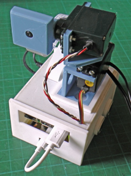
The finished unit looks like this
Camera sits in this box which pivots on the tilt servo. I’ve abandoned the LED ring light I used previously as its ligh is just not bright enough to be of any use further than a few inches from the camera.


Pan servo.

5-


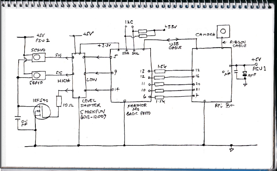
Circuit diagram
The circuit is fairly straightforward. The Rpi communicates with the Feather by 5 GPIO pins. I have included 1.5k resistors in case both processors are accidentally set to output and there is contention with one trying to output high, the other low. The Feather and the Rpi can also communicate over serial/usb. The Feather uses two pins to control a couple of radio control servos. The servos nominally work at 5 volts but they will operate at 3.3 volts on their control connection. However, to be on the safe side, I have included a 3.3/5 volt level shifter. The power to the servos is switched on and off by a mosfet connected to a Feather pin (again via the level shifter). The servos can be left buzzing as the motors don’t quite shift the reference potentiometer enough to switch it off. This doesn’t seem like good for long term reliability so I have arranged for the software to be able to turn off the power. I would have preferred to have had the switch in the high side of the supply to the servos but that would have slightly complicated matters. The servos jiggle a little when the mosfet switches on. Perhaps the high side switch would have alleviated this but I didn’t try this out on the bread board.
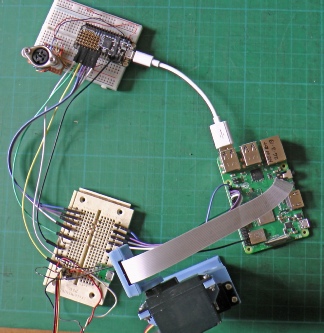
Talking of bread boarding, the pic on the left shows this being carried out.
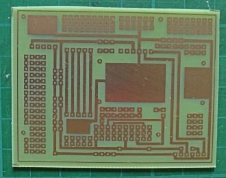
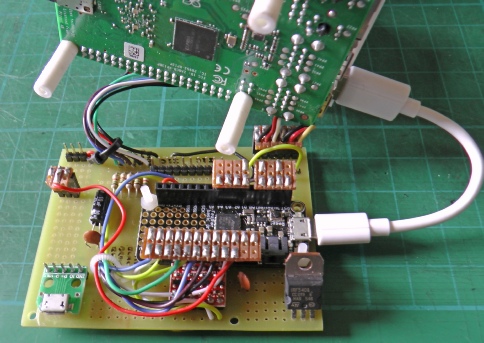
The next thing to do was to design a pcb. As usual, I filled in unused areas with spare pads. The solid blocks of copper are under components making them unsuitable for spare pads. Including the copper saves on etchant use and might act as shielding (if it is joined to ground).
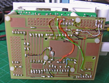
Left above, the parts are soldered to the pcb. I have made connectors out of male and female headers and strip board (Veroboard). Above right shows the rear of the pcb with the usual afterthoughts and additional connections!
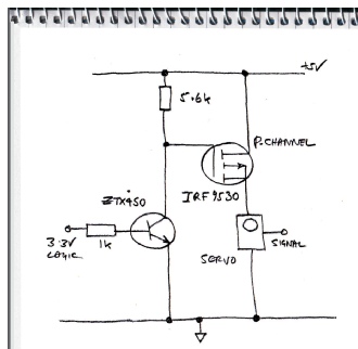
If I had used the circuit on the right, I could have probably left out the level shifter. Incidentally, P-
The next page describes the manufacture of the case.