


Under Construction
Radiometer 1
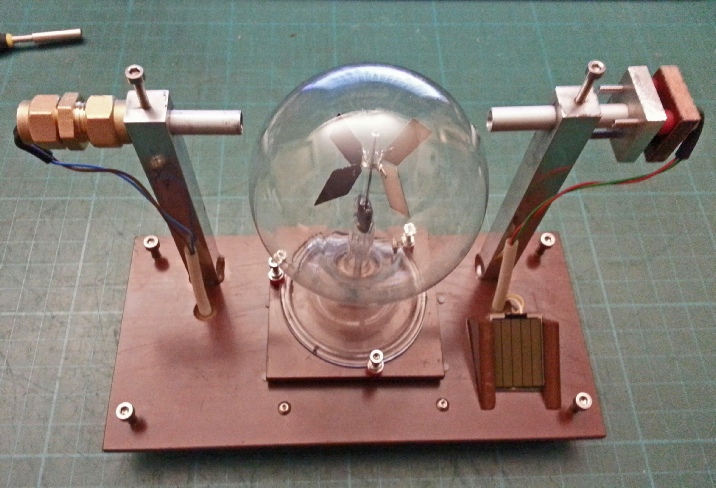
This project attempts to use a Crookes Radiometer novelty toy to make a sunlight detector to add to the elements of my weather station. The radiometer was invented by Sir William Crookes and consists of four vanes which can rotate in a partially evacuated glass bulb. The vanes are black on one side and white on the other. In sunlight they revolve, the speed of rotation increases as the intensity of the light increases so by measuring this speed the electromagnet energy of the light might be measured. I think this device is not directional and not affected by the position of the Sun which could be important in any measurement. (Although I am not anticipating any great accuracy here!). See here for further details including how it actually works.
I have included a small photo-
I am measuring the speed of the vanes by setting the radiometer up so that the vanes break a light beam. This is detected and the information is sent over I2C to a microprocessor in the base station (as is the voltage generated by the photo-
I’m not sure how I will process any data I manage to collect over a period of time. I’ll think about that later! The circuit is below.
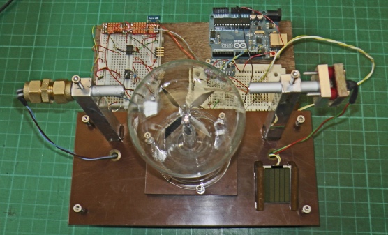
I was aiming at a Victorian/Edwardian scientific instrument look here. Tufnol, which I have used for the base has a retro look (it is, after all, a relative of Bakelite) and also hints at mahogany. The supports for the laser diode and the photo diode sensor are made from ½” square aluminium bar drilled out to 8mm to take the aluminium tube (B&Q) which holds the diodes. The bases of the supports are drilled and tapped to M4 thread. I drilled corresponding holes in the Tufnol base. I then passed an 8mm tube through both holes to ensure they were correctly aligned put some epoxy under each support and tightened the screws securing the supports to the Tufnol base but not too tightly so that when the epoxy hardened, the supports would remain aligned. In the picture on the left you can also see a couple of triangular supports for the photo-
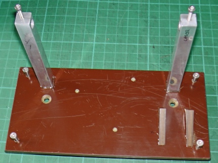
Underneath, you can see the screws securing the supports, holes for wires and four feet which consist of silicon rubber tube over M3 screws (which should be ajdusted to not quite come to the end of the tube).
A low power laser diode is pressed into a square of tufnol. The tufnol is screwed to a matching piece of aluminium (by three screws threaded into the aluminium). Small pieces of silicon rubber tubes threaded on the screws act like springs between the tufnol and the aluminium. By adjusting the screws, the aim of the laser diode can be set.
8mm aluminium tube to hide the output of the laser diode from direct view and on the other side shade the photo-
The photo diode is contained in an 8mm plumbing compression joint which holds it nicely.
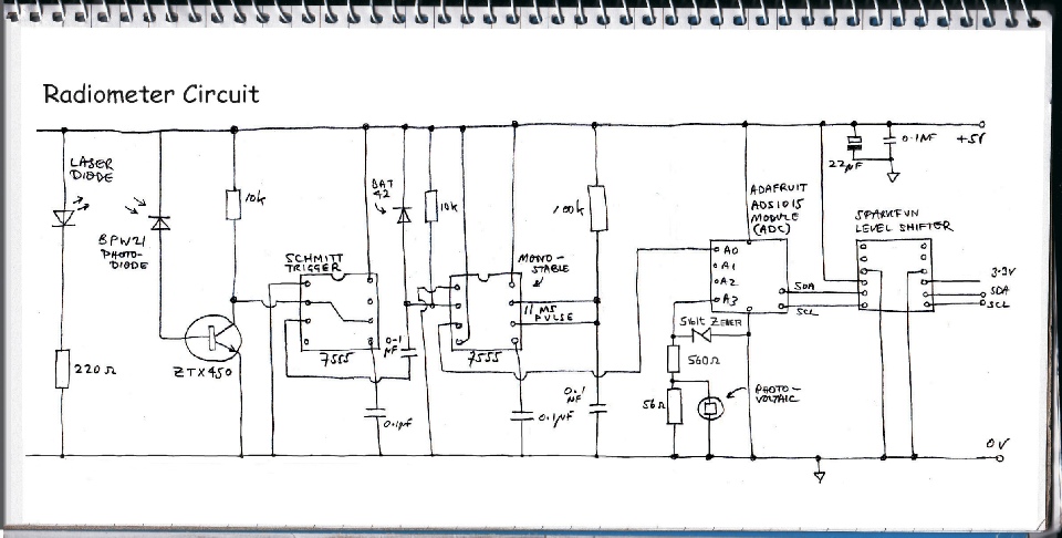
The circuit uses a cheap laser diode (99p on eBay) to shine a beam through the glass bulb of the radiometer. A photo diode detects the beam which is positioned to be interrupted as the vanes rotate. The diodes are in tubes to avoid interference fro daylight etc.
The circuit seems to be rather similar to ones I have used before in other projects in that it features a couple of 555 timers (or the cmos derivatives). I suppose when you are converting a rather slow changing characteristic such as the interruption of a light beam by a mechanical device rotating at 200 rpm at the most, into a signal which is relatively unambiguous to a digital device, you are going to use the slow changing signal into some nice clean square pulses.
The first 555 is connected as a Schmitt Trigger which turns the signal from the photo diode (amplified by the transistor) into an output which is either 5 volts or 0 volts with nothing in between. (Nothing which could be detected by the subsequent circuitry, at least, because the voltage transition is so fast.)
The second 555 receives the signal from the first via a 0.1 microFarad capacitor a 10k resistor and a diode. This is known as a differentiating circuit and it turns the rectangular pulses from the first 555 into short, spikes, of a positive and negative going nature (again, see here). The negative going spikes trigger the second 555, which is wired as a monostable (which means it only produces an output if it is triggered). The pulse output by the second 555 is about 11 ms long (the length of the pulse is determined by the 100k resistor and the 0.1 microFarad capacitor).
If I had included a micro in the circuit (such as an Arduino Uno of a Feather) I would have just counted these pulses over a fixed period to get the rpm of the radiometer vanes. However, I wanted to connect to a remote computer and at the same time measure the analogue output from the photo-
I could lengthen the pulse (by increasing the value of the 100k resistor or 0.1 microFarad capacitor) but then I might run into a situation whahigh rpm, where the 555 was trying to trigger before the pulse had time to complete. Anyway, I’ll see how it works. I could video the vanes tuning, make a note of the circuit’s output and check the actual rpm by loading the video into editing software and simply counting the revolutions.
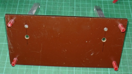
Below is a picture of the completed unit being tested with a bread-
Photo-

Separate base for the radiometer with three levelling screws which drop into corresponding holes on the main base.

Next, the PCB and completion of the construction with some initial software.
The circuit on the radiometer has been superseded by a mk2 version available here!