


Under Construction
Rain gauge circuit and software
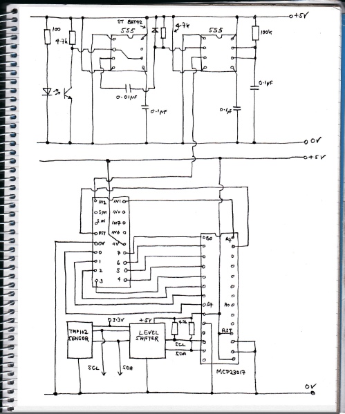
Circuit
I am using a slot-
The answer is add a Schmitt. I often resort to the trusty 555 timer which can be wired up to do this job without any extra components. To complete the signal processing, I will use the output of the Schmitt to trigger a monostable circuit (also using a 555 timer) to produce a fixed length pulse of about 11 mS which, hopefully, will avoid any confusion on the part of the microprocessor which will be counting the pulses. To simplify things slightly I will use a 556 chip which is two 555 circuits in one package.
The eighteen pin chip under the 555s (556 actually) on the left is a PICAXE 18A which is a Microchip PIC16F819 microprocessor pre-
In this particular case a program of a few lines can get the PICAXE to count the pulses emanating from the 556. The count is registered as an 8-
Alternative schemes
My PICAXE 18A is now redundant and newer versions have I2C facilities. In an I2C network there can only be one master, other devices connected have to be configured as slaves. I haven’t investigated whether these PICAXEs can be configured as slaves.
Arduino Unos, however, can be configured as slaves. The slave can be configured to do stuff like count events and transmit the current value when requested by the master. I have bread boarded this and it works fine. (The 556 would still be needed if I were using the slot-
Using a whole Uno for this would seem to be a waste! I tried an Adafruit Trinket which would seem to be ideal but couldn’t get it to work. I’ve had trouble with the Trinket and I2C before. I could get it to read one TMP102 temperature but not two (they were set to separate addresses). It’s probably just me -
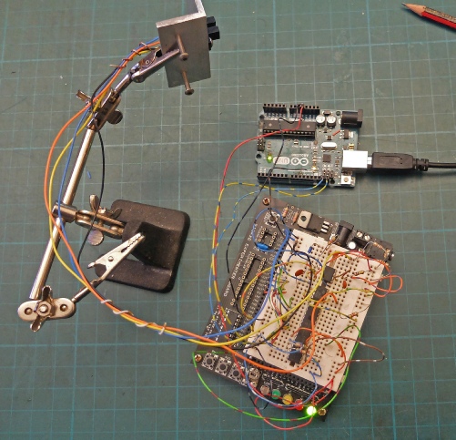
Back to the original concept! The picture on the left shows the circuit on a breadboard. The breadboard is one specially designed for PICAXEs
555s (I used individual ones here!)
MCP23017
PICAXE

Slot-

Arduino Uno

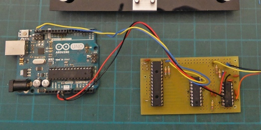
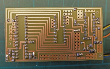
Circuit on a pcb connected to an Uno for testing purposes
The pcb didn’t need the usual modifications for once!
//test port expander inputs on breadboard BASIS for RAIN GAUGE
//picaxe 18A is counting (8-
//the signal is conditioned by a Schmitt trigger and a monostable (556 IC)
//Feather reads the value periodically
//20.1.18
// pin 6 (a6 on chip numbering) is connected to picaxe reset pin (needs to be high to run)
// pins 8 to 15 (b0 to b7 using chip numberings) are used to log the count from the picaxe
// The input to the Picaxe from the 556 is on input 2
// input 1 is connected to pin 7 on the MCP23017 (a7) for possible future use
#include <Adafruit_MCP23017.h>
#include <Wire.h>
Adafruit_MCP23017 mcp;
byte b0, b1, b2, b3, b4, b5, b6, b7;
int val;
#define TMP102_I2C_ADDRESS 0x48 // I2C address TMP102 A0 to GND (0x48 = 72 = 1001000 for GND, 73 for vcc)
#define TMP102_I2C_ADDRESS_2 0x49 //second tmp102
void setup() {
mcp.begin(1); // use address 0x21 (0,0,1) rather than default
Serial.begin(9600);
mcp.pinMode(8, INPUT);
mcp.pinMode(9, INPUT);
mcp.pinMode(10, INPUT);
mcp.pinMode(11, INPUT);
mcp.pinMode(12, INPUT);
mcp.pinMode(13, INPUT);
mcp.pinMode(14, INPUT);
mcp.pinMode(15, INPUT);
mcp.pinMode(6, OUTPUT);
mcp.digitalWrite(6, HIGH);
}
int getTemp102(byte ADD_TMP102){
byte firstbyte, secondbyte; //these are the bytes we read from the TMP102 temperature registers
int val; //an int is capable of storing two bytes, this is where we "chuck" the two bytes together.
float convertedtemp; //We then need to multiply our two bytes by a scaling factor, mentioned in the datasheet.
Wire.beginTransmission(ADD_TMP102); // start talking to sensor
Wire.write(0x00);
Wire.endTransmission();
Wire.requestFrom(ADD_TMP102, 2);
Wire.endTransmission();
firstbyte = (Wire.read());
//read the TMP102 datasheet -
//each of the temperature registers on the TMP102
secondbyte = (Wire.read());
//The first byte contains the most significant bits, and
//the second the less significant
val = firstbyte;
if ((firstbyte & 0x80) > 0) {
val |= 0x0F00;
}
val <<= 4;
//MSB
val |= (secondbyte >> 4);
// LSB is ORed into the second 4 bits of our byte.
convertedtemp = val*0.625; // temp x 10
int temp = (int)convertedtemp;
return temp;
}
/////////////////////////////////////////////////////////////////////////////
void loop() {
b0 = mcp.digitalRead(15);
b1 = mcp.digitalRead(14);
b2 = mcp.digitalRead(13);
b3 = mcp.digitalRead(12);
b4 = mcp.digitalRead(11);
b5 = mcp.digitalRead(10);
b6 = mcp.digitalRead(9);
b7 = mcp.digitalRead(8);
val = b7 * 128 + b6 * 64 + b5 * 32 + b4 * 16 + b3 * 8 + b2 * 4 + b1 * 2 + b0;
Serial.println(val);
int tempNow2 = getTemp102(TMP102_I2C_ADDRESS_2);
Serial.println(tempNow2);
delay(1000);
}
/////////////////////////////////////////////////////////////////////////////////
The software below runs on a Feather connected up for testing purposes. The program reads the count on the PICAXE every second together with the temperature registered on a TEMP102 sensor. Eventually, similar software will be incorporated in the overall monitoring and control system.
// test master slave I2C Arduino
// this is the master
#include <Wire.h>
#define DEV_ADD (0x10)
void setup() {
Wire.begin();
Serial.begin(9600);
}
void loop() {
Wire.beginTransmission(DEV_ADD);
Wire.requestFrom(DEV_ADD, 1); //request 1 byte
Wire.endTransmission();
byte count = (Wire.read());
Serial.println(count);
delay(3000);
}
// test master slave I2C Arduino
// this is the slave
#include <Wire.h>
#define DEV_ADD (0x10)
int count;
void setup() {
Serial.begin(9600);
Wire.begin(DEV_ADD);
Wire.onRequest(reqHandler);
}
void reqHandler() {
Wire.write(count);
}
void loop() {
count++;
delay(500);
Serial.println(count);
if( count == 255) {
count = 0;
}
}
For the sake of completeness, the programs I used to link two Unos over I2C are shown below.
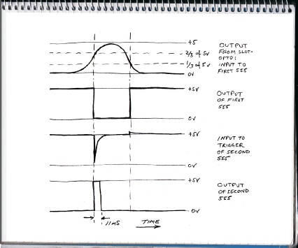
These are the waveforms I expect to get from the slop-
Waveform 2 shows the output of the first 555. Pins 2 and 5 are connected together as the input. When the input voltage is rising, once it reaches 2/3 of the supply voltage, pin 6 causes the output to go to zero. When the input is falling, once it reaches 1/3, pin 2 causes the output to go high to the supply voltage.
1
2
3
4
Thus a relatively slowly varying voltage is converted into square wave which is either on or off but nothing in between. These are the sorts of waveforms digital computers like!
Next the output is passed on to the second 555 via the 0.01 micro Farad capacitor and the 4.7k resistor network. Capacitors can only pass voltage changes not steady voltages hence the negative-
I love the 555 which I use at every opportunity! It’s probably because it’s a bit complicated but not so complicated that I can’t understand all its little foibles, with a bit of effort! (A bit like the BBC ‘B’ computer -
Software
'counter for rain gauge
pins = 0
b2= 0
main:
if pin2 = 1 then add
goto main
add:
b2 = b2 + 1
pins = b2
pause 200
goto main
Left is the very simple program for the PICAXE written on the editor provided by Revolution Education, the suppliers of the PICAXE. “pins” is a byte variable whose bits are mapped to the eight output pins of the PICAXE. “b2” is a built-
PICAXE programming revives the good old “goto” that we used to know and love before structured programming (thanks to Mr Dijkstra).