


Under Construction
Wind direction indicator 1
The main part of the wind direction indicator will be a device to generate a digital signal in response to the way a wind vane is pointing. The device in question is known as a rotary encoder. How precise the indication will be is determined (amongst other things) by the number of bits in the output of the encoder. I want to distinguish sixteen different directions (N, NNE, NE, ENE etc.) and so I will need to generate a four bit number.
Rotary encoders are often devices with optical sensors. A light shines through a disc and is detected by a photo-
If the code is represented as a binary number, that is:
number = digit_3 * 8 + digit_2 * 4 + digit_1 * 2 + digit_0
then a nifty four lines of code involving bitwise XORs and bitwise shifts converts it into a true binary representation of a number. (I just can't see how anyone could work out this code except by trial and error which probably says a lot about my thinking skills!)
In designing this device, I have a few things in mind.
1. My ability to produce precision engineering is limited by a lack of equipment (and possibly skill) so any design will have to take this into consideration.
2. The equipment will be out in all weathers. Since there will be rotating parts protruding fom the device into that weather, the ingress of water and water vapour is inevitable.
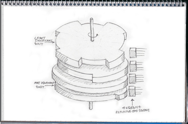
I've decided to be a bit different and not use a disc which might acquire blobs of water either on the disc or on the sensors or light source. Instead, I am going to use reflective sensors acting on a cylinder with the zeros on the four tracks represented by what are essentially holes (which do not reflect). I am going to make the cylinder from four 60mm diam discs cut from 3mm aluminium sheet with three spacers, also from 3mm sheet.
Back to the mechanical aspect, the wind vane will probably need a damper. The simplest option is probably a disc running in an oil bath.
t
Now for thoughts about the circuit. The sensors I am using are type QRD1114. The phototransistor responds to infrared light with an output current dependent on the intensity of the light. This means it can hover between “on” and “off” which can confuse a digital input. A Schmitt trigger circuit cures this as its output is either on or off (1 or 0) and nothing in between. In addition it has hysteresis. This means that the output switches off and on at different input voltages which eliminates any fluttering between on and off during a transition.
I usually use a 555 (actually 7555 low power version) connected as a Schmitt. It has a wide hysteresis and this is place midway between zero volts and the power supply voltage. This is how it works. The output switches on (digital 1) when the input drops below one third of the supply voltage and switches off (digital 0) when the input moves above two thirds of the supply. It should be noted that when used like this the 555 is an inverting device. This works well with the photo-
I want to connect to the control computer by I2C so a port expander chip, mcp23017, will do the job, albeit with a great waste of capacity.
The QRD1114 and the 7555s would probably work at 3.3volts supply but I feel more confident using 5volts. Also the LEDs on the sensors will draw about 50mA and my 3.3 supply is derived from the regulator on the microprocessor board so 5 volts it will be. This means I will need a logic level shifter.
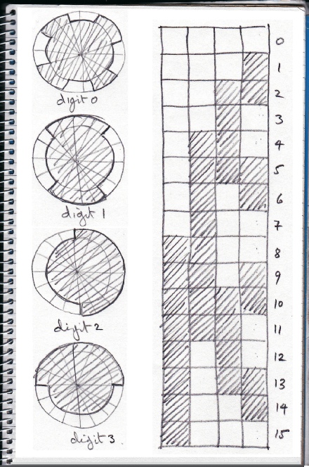
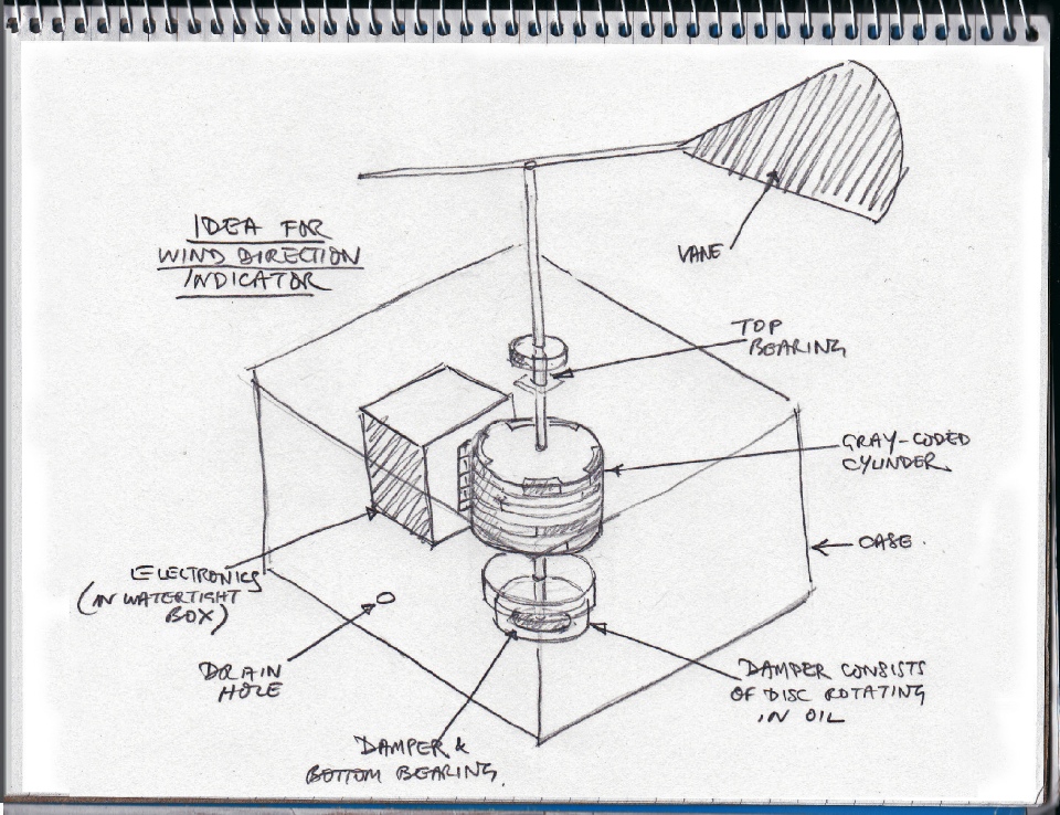
Left is (a rather poor) sketch of how the indicator will work. The discs are cut to provide reflecting and non-
Below right is the layout of the reflecting surfaces (shaded) peeled off from the surface of the stack of discs as it were, to provide the Gray code position information. The discs themselves are shown on the left.

Traditional wind direction indicator
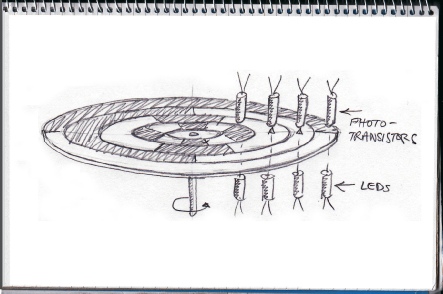
Below, typical disc arrangement with light transmitted through the disc with detection by photo-
The details of the electronics comes next.
Below is the basic idea of how the complete unit would look.