


Under Construction
Wind direction indicator 2
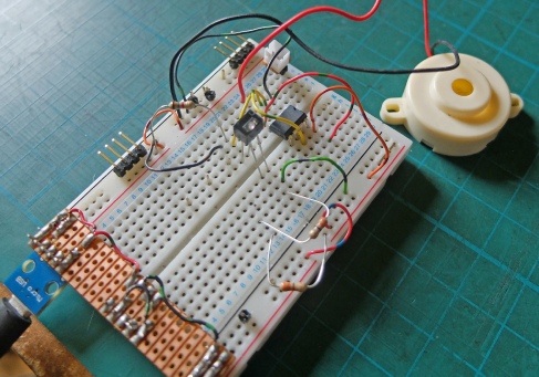
Left is a breadboard setup to test the basic concept.
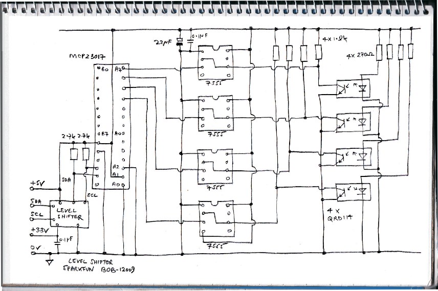
The circuit below follows the ideas I set out on the previous page. The only fiddly bits are the values of the resistors for the transistor collectors and the LEDs. The LEDs don’t want to be too bright or the transistors too sensitive. The smaller the value for the LED, the brighter the LED. The larger the collector resistor, the more sensitive that part of the circuit. The value of the collector resistor needs to be large enough to swing its voltage below 1/3 of the supply voltage, that is about 1.6 volts. The values chosen seem to work, so far.

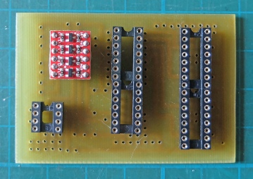
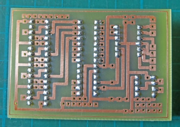
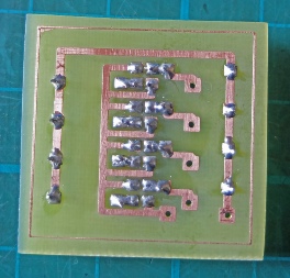
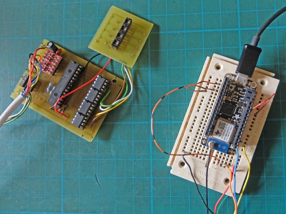
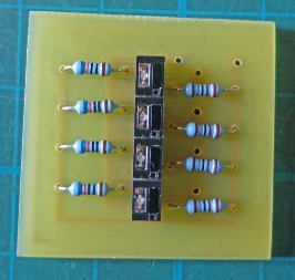
Below left is the pcb I designed for the main electronics. Centre and right shows the pcb for the sensors. I realised that I had been stupid in putting the resistors on the same side as the sensors as they prevented the sensors projecting far enough through the case. I moved then to the track side.
Above, the sockets for the ICs and the Sparkfun level shifter. I included an extra 7555 Schmitt (bottom left) for an input from a wind speed sensor (yet to be finalised).
Right the pcb and the sensors being tested with an Adafruit Feather.
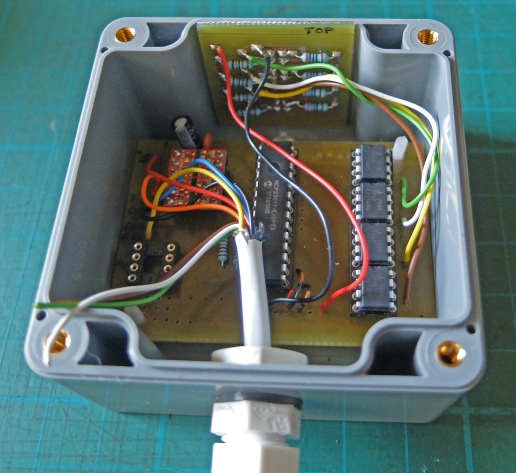
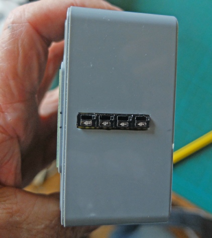
Above, the pcb trial fitted in a water-
// ****************************************************************************
// * wind_drctn_test2 tests wind direction pcb
// * By Julian Rogers 17.7.18
// *****************************************************************************
//libraries
#include <SPI.h>
#include <Wire.h>
#include <Adafruit_MCP23017.h>
byte b0, b1, b2, b3, b4, b5, b6, b7, num, old_num = 0;
Adafruit_MCP23017 mcp2;
//-
void setup() {
delay(1000);
Serial.begin(9600);
while (!Serial) {
Serial.println("waiting for serial..."); //Needed for native USB port only but if used waits until serial monitor opened
//Also used for diagnostic purposes
}
Wire.begin();
mcp2.begin(2); // use address 0x22 (0,1,0) rather than default for rain gauge
Serial.println("starting...");
mcp2.pinMode(0, OUTPUT);
mcp2.pinMode(1, OUTPUT);
mcp2.pinMode(2, OUTPUT);
mcp2.pinMode(3, INPUT);
mcp2.pinMode(4, INPUT);
mcp2.pinMode(5, INPUT);
mcp2.pinMode(6, INPUT);
mcp2.pinMode(7, INPUT);
Serial.print("reading... ");
Serial.println("0");
}
//-
// Functions start here
byte GrayToBinary(byte num){
// "magic" conversion routine!
num = num ^ (num >> 8);
num = num ^ (num >> 4);
num = num ^ (num >> 2);
num = num ^ (num >> 1);
return num;
}
// End of functions
//-
void loop() {
b0 = mcp2.digitalRead(4);
b1 = mcp2.digitalRead(5);
b2 = mcp2.digitalRead(6);
b3 = mcp2.digitalRead(7);
num = b3*8 + b2*4 + b1*2 + b0;
num = GrayToBinary(num);
if(num != old_num){
Serial.print(b3);
Serial.print(b2);
Serial.print(b1);
Serial.println(b0);
Serial.print("reading... ");
Serial.println(num);
Serial.println("");
}
old_num = num;
delay(50);
}
//-
Below is a test program for the circuit, printing out the “raw” ones and zeros and the converted value.