 Home
Home


The software is surprisingly long for what would seem on the face of it quite a simple device. This seems to suggest that my software is not very compact or efficient and I make absolutely no claims about this or about the elegance of my programming style! Also, the program constantly runs up against warnings about the space taken up by variables and I have done my best to minimise this but undoubtedly many improvements could be made. However, It does have the virtue of working reliably over a period of months with no crashes or unexpected events.
The main function of the software is to know the current time and have a list of on/off times and desired temperature levels stored in a non-
The on/off times and desired temperature levels are stored on an SD card on the Ethernet shield. The temperature registered by the sensors is also stored in a log file on the SD card.
The system employs User Datagram Protocol (UDP) to receive instructions from a program running on a remote computer and reporting back its current status.
I have only developed a simple Processing application which can upload on/off times, upload temperature settings and adjust the clock if required. It can receive confirmation of these data and the current temperature, the position of the switches and whether advance is in operation. This aspect needs development with a nicer user interface etc. (see below)
(Michael Margolis deserves credit for aspects of UDP and Processing which I have cribbed from his Arduino Cookbook -
Download a PDF of the Arduino program here.
Download a PDF of the Processing program here.
Timer software
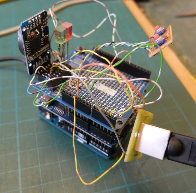
“Mule” used to test software and circuit modifications “on the bench”.
Real time clock
“Advance” buttons
Prototype shield
Ethernet shield
Arduino Uno
Connection to temperature sensor.
Usb to desktop PC


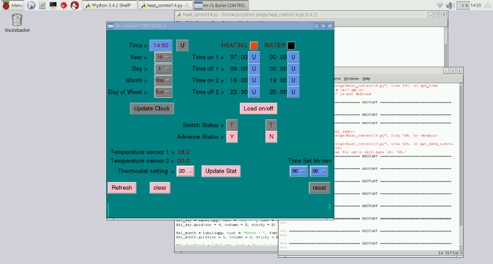
Below is a screen shot of the Python control program which uses a Tkinter GUI. It looks like Visual Basic for Windows from the 1990s but it works ok! Again, it uses UDP to talk to the timer. I have run this on a PC and on a Raspberry Pi. (The Pi sometimes has some difficulty receiving data from the controller, timing out on the sock.recv() command from time to time. Perhaps it’s my programming.)
In operation, pressing the “Refresh All” button loads the current values stored on the timer. To change an on/off time, you enter times using the option menu buttons on the right near the bottom, then press the appropriate “U” button to load the time in the heating & water on/off grid. Pressing the “Update on/off” button sends the new times to the timer. There is provision to set the timer’s clock, set the thermostat and see the “advance status” and control switch positions on the timer as well as the temperature recorded by the sensors.
The Python program can be downloaded as a PDF here. Apologies for the lack of style and lack of OOP but this is my first Python program of any substance!
Software development
Further work could involve storing different on/off times for different days of the week. One problem is that the memory storage for variables on the Arduino is close to the limit for reliable operation. I need to make the Arduino software more efficient if possible.
Alternatively, the times could be stored on a PC and sent to the Arduino when required. The PC would need to be on all the time, running the control program to enable this to work..
My plan is to run the more advanced control software on a Raspberry Pi, hopefully with a 7 inch touch screen interface.
Control program running on a Raspberry Pi
Update:
The touch screen 7” Raspberry Pi display has arrived! It is bright and sharp and the touch screen works very well. However, there are not enough pixels to display all of my Tkinter GUI. I will have to slightly redesign the software to get everything in.
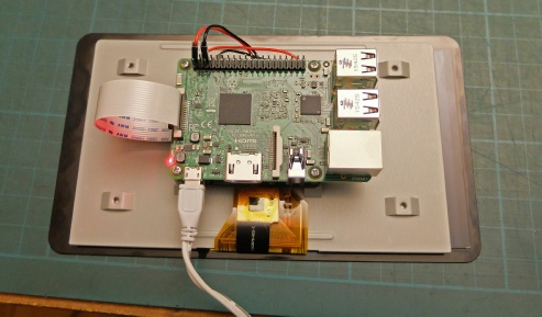
Raspberry Pi 3 sits over the interface PCB for the display.

Ribbon cable joins PCBs together
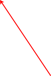
Important bits of the GUI are now off screen!

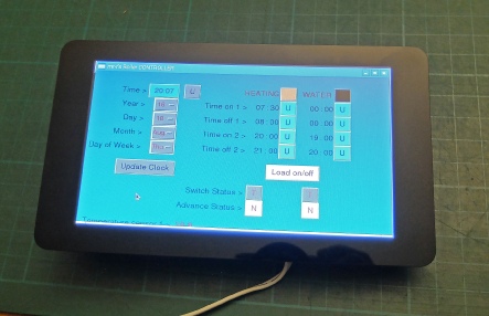
By leaving out the clock adjustment menus (the clock should keep accurate time, shouldn’t it?) And rearranging the buttons etc, I have got the essential controls (as I see it anyway) on the screen.
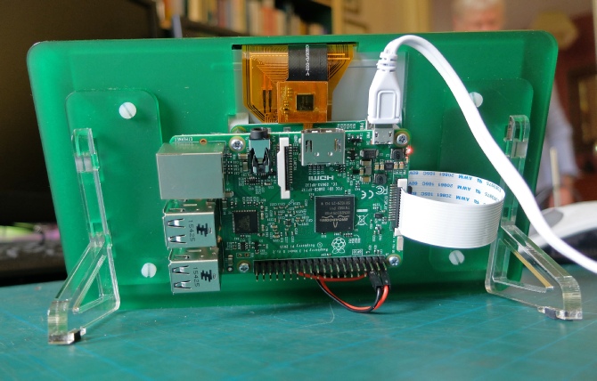
Quite nice frame and stand from Pimoroni. A case will be needed eventually.
Timer construction details next…