
 Home
Home

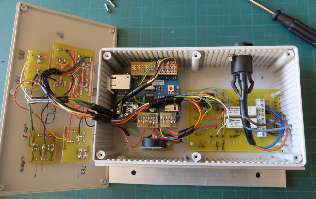


The case is from Maplin (because there is a branch nearby -
I design my PCBs using free DesignSpark software. I generally don’t use auto-
I print out the designs on inkjet transparency film from Rapid Electronics. I generally stick two designs together to ensure the best opacity. 2½ minutes in my UV box does the trick.
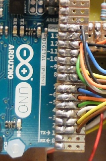
To connect to the Arduino, I use pieces of copper strip board (Veroborad) with headers soldered on. I pass multi-
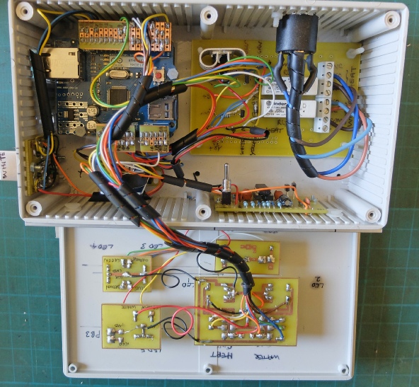
The system shown above is not quite complete because in this picture I have not yet fitted sockets for the temperature sensors. The sockets and cables I have used are RJ45 network types as they are really cheap. The sensors communicate by I2C and need SDA, SCL, 5 volts, 3.3 volts and ground so a five-
Apparently I2C is intended for short-
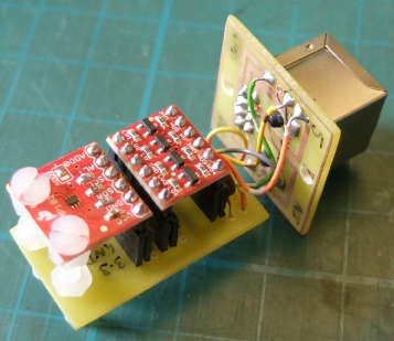
Shown on the right is my prototype temperature sensor. It uses an I2C sensor breakout board and logic level translator (3.3 to 5 volt etc.) from SparkFun.
I have plugged the boards into a PCB using headers and that makes it too bulky. Next time I will solder the wires directly to the boards and design a more compact board to connect to the RJ45 socket.
Incidentally, I have not provided a temperature adjustment on the sensor itself for simplicity (and also to prevent tampering!) Simple implementation of such a feature might be tricky. It would have to be done digitally because of the problem of voltage drop in a long cable with analogue. (Although 4-
Timer construction

Next: PCB layout
Further developments
After running the timer for about six months, I found there were a couple of occasions when the Arduino hung up and needed to be reset. Exactly why this should happen is not clear but it could be connected with memory being over-
To prevent this being a problem, I have fitted a watchdog timer which resets the Arduino if a hang up is detected.
I have described the watchdog timer here.
The watchdog monitors pulses on pin 2 which is Tx for serial communication. If nothing happens for about two seconds, the watchdog takes the reset pin to zero volts for about 0.01 seconds.
Watchdog timer


Ethernet shield on top of Arduino
7805 regulator
230 VAC rated socket
Relays & ZTX450 drivers
Real time clock
PCBs for switches & LEDs