 Home
Home


Circuit for the boiler
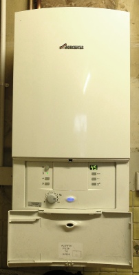
My boiler is a relatively modern Worcester non-
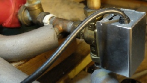
Also in the mix is a three port valve which can send hot water to the hot water cylinder or the radiators or both. In addition there is a tank stat and relay and a room stat.
Boiler
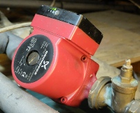
Pump
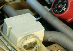
Mains rated SPDT relay
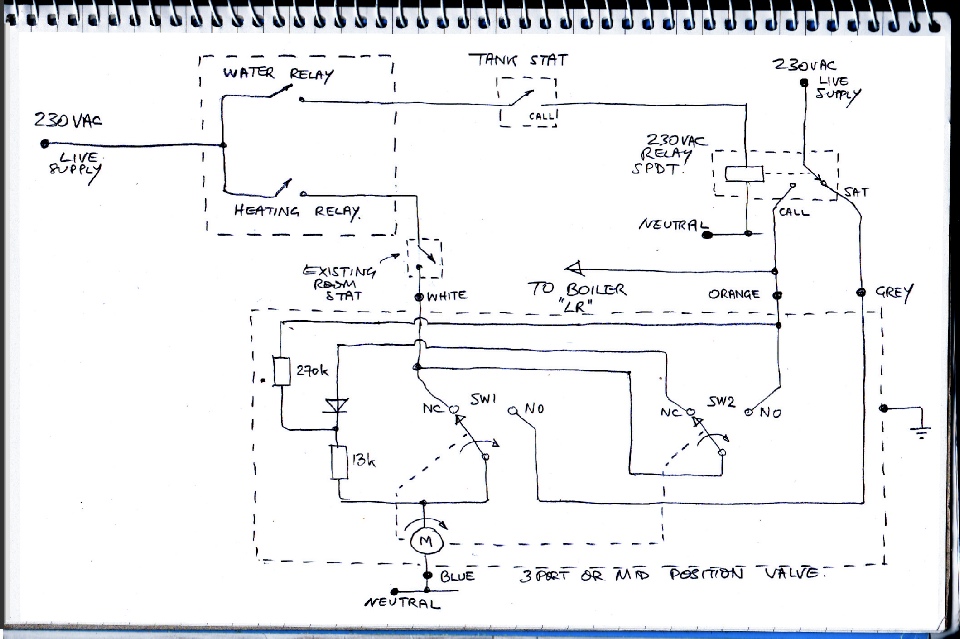
The circuit in a way revolves around the three port, or mid position or 5-
The roomstat could be deleted given that the timer has its own sensors but I like to keep it in so that I can return to my old system in emergencies etc. If kept, it needs to be turned right up to avoid interfering with the new system.
The valve and the relay will probably be close together. A junction box is needed to connect up all the wires. I use a twin-
The relay is a fairly hefty unit, probably quite old, which came with the house. If I was starting from scratch I would probably make a PCB with a PCB relay and connectors etc custom designed for the connections required. However, you’ve got to stop somewhere!
Ours is a fairly large rambling house and a single thermostat will not do a good job of controlling the system. Radiator stats do a reasonable job but what is really needed is motorised valves on radiators or at least on zones. That way rooms which may be out of use on certain days etc. will not be needlessly heated. This gets fairly complex and expensive but is a project I have in mind. (But I have many such mental projects…)
Next: timer software…