Home
Home


TR7 gauges part 3
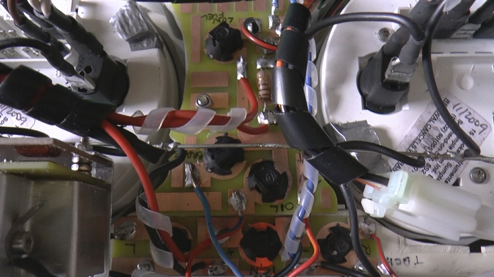
The picture below shows how the wiring progressed. I had stretched an 18 swg piece of tinned wire across the back of the unit from one gauge fixing screw to another. This was connected to the chassis and acted s a handy place to solder earth/chassis connections. (To make a piece of wire dead straight, put one end in a vice, hold the other end with pliers or a Mole wrench and pull till you feel it yield slightly. It will then be straight and reasonably stiff.)
I use a lot of spiral wrap. You can get a rather firm version from Rapid Electronics or a more pliable kind on Ebay. Spiral wrap and adhesive lined heat shrink tubing are my BFFs when it comes to wiring. (But please use a heat gun rather than a soldering iron (see Ed China) with the heat shrink. I use a B&Q paint stripper gun. It needs to be used carefully though as it pumps out a lot of heat energy. Always unplug after use to avoid accidental switch on as it could easily cause a fire. On that note, it’s excellent for encouraging a fire in our grate which does not enjoy a great draft from our chimney.)
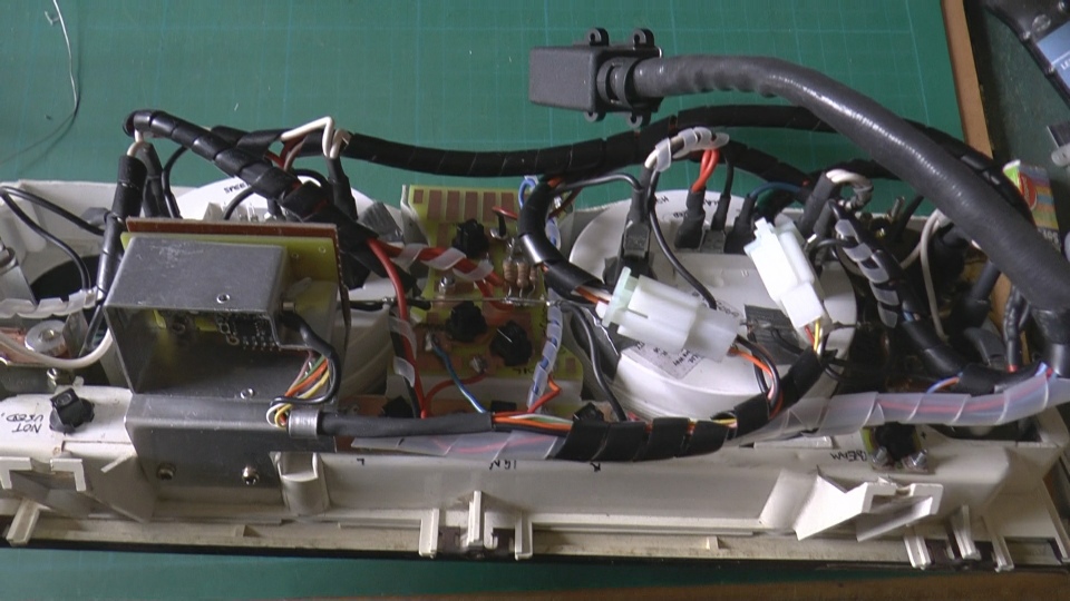
The picture below shows a wider angle view of the back of the unit. It also shows the PCB that powers the new stepper motor fuel gauge using an Adafruit Trinket microprocessor board.