Home
Home


Speedometer sensor
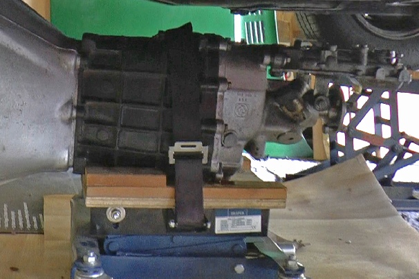
Bracket which holds sensor is bolted to this hole in the gearbox which is an unused mounting point.


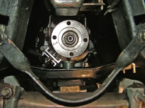
Drill two holes 180 degrees apart into the edge of the gearbox output flange to take two rare earth button magnets supplied with the speedo. They should be fitted with the dimple facing outwards to ensure their poles are pointing in the right direction. Because of the power of the magnets once in the hole they stay in the hole but a bit of epoxy can’t do any harm.
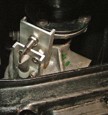
I mounted the sensor on a couple of pieces of shallow aluminium channel. The first is bolted to the gearbox (there is an existing treaded hole in a handy position) and the second is bolted to the first with spacers to get it the right distance from the flange for the sensor which is threaded for adjustment. If you get the sensor to near to the flange, it picks up randomly on the metal and the speedo can say you’re doing 70 when you’re only doing 30! It definitely needs to be more than the 4mm in the instructions.
Follow the instructions for calibrating the speedo. I checked mine with a sat-
The ETB speedometer comes with a Hall-
The sensor needs to pick up from a part of the car whose rotational speed is proportional to the road speed. It will pick up from bolt heads but I chose to use magnets fixed to the output drive flange of the gearbox.
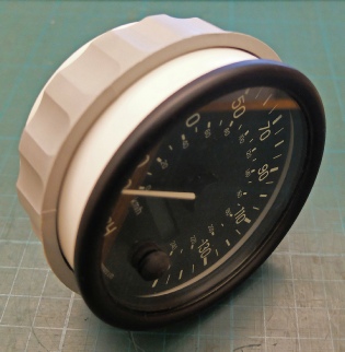
100mm ETB speedometer
This button resets the odometer and enables the speedo to be calibrated