

 Home
Home

Under construction
PCB to allow the RPi to control four relays and measure temperature over the I2C interface
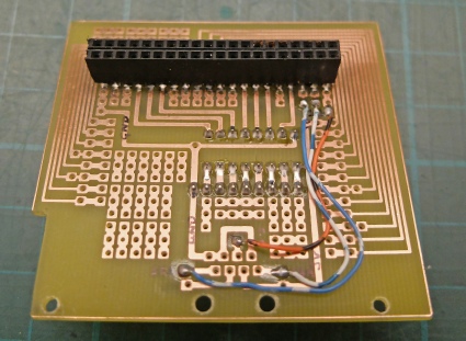
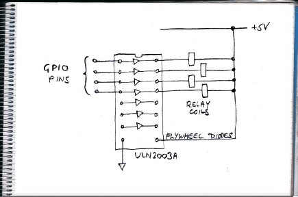
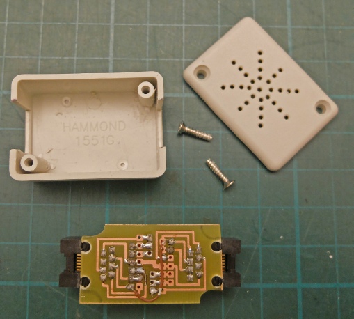
This is the pcb which implements a straightforward circuit which links a ULN2003A Darlington transistor array with GPIO pins on the RPi. The Darlintons boost the voltage and current from the GPIOs so that 5 volt relays can be turned on and off. The IC also has built in diodes to guard against reverse votage generated when the relays turn off (“flywheel diodes”). The pcb also provides an RJ45 socket connected to the I2C pins on the Pi which can be connected to one or more I2C temperature sensors (TMP102).
I originally designed a general purpose pcb which brought all the GPIO pins round a central prototyping area. When I added the ULN2003A I left the tracks for the other GPIO pins in place although they aren’t really needed. These tracks, by the way, are as about as fine as I would trust my making methods to reliably produce!
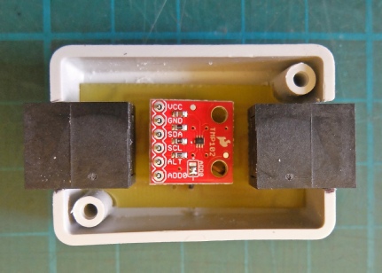
The temperature sensor is a TMP102 on a Sparkfun breakout board which I have used in other projects. I have connected a second socket to allow another I2C device to be attached.
Temperature sensor
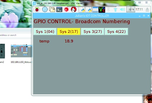
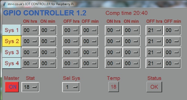
A screen shot of the Pi working with the relays and the TMP102 is shown left.
To get I2C working on the Pi, first you have to make sure that I2C is enabled in Raspberry Pi configuration, Interfaces.
Then type the following in a terminal window:
sudo apt-
sudo apt-
sudo apt-
Sudo apt-
The Python program, which is a development of the one shown on the previous page, can be found here.
A developed version incorporating four timers and advance functions plus a thermostat is here. (See later for a fuller description.)
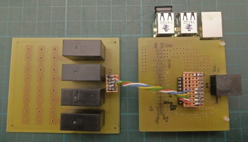
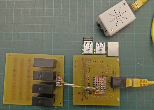
The relay board is a separate pcb mainly to keep mains voltage away from the Raspberry Pi and also to allow more flexibility when fitting the whole shooting match in a box. The relays are 5 volt, 16 amp types, Rapid Electronics number 60-
The 40-
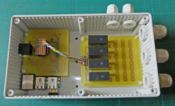
The Pi, the interface pcb with the Darlington driver chip and the relay board in its case.
(Most of the Pi is covered by the pcb, of course.)
Screen shot of the Python/Tkinter control software running on the Pi.
The thermostat function operates on any one channel selected by the Sel Sys option menu. There is a delay in the switching of the thermostat-
An advance to the next setting facility is available for each channel.
The settings are saved to file and automatically loaded when the program restarts.
There is a master switch which turns all four channels on or off at once. There is also a status display which can flag up a number of errors, should they arise.
I don’t think this is a very well-
Second socket to allow more I2C sensors etc to be connected.

Sparkfun breakout board

I use RJ45 cable to connect the I2C sensor.