 Home
Home

Old phone on the mobile network
//development of dial input
//10.6.16
byte digit = 0;
byte tele_num[13];
byte count = 0;
void setup() {
//using INPUT_PULLUP obviates the need for an external pull up resistor
pinMode(2, INPUT_PULLUP); // this is connected to contacts which open & close as the dial turns
pinMode(3, INPUT_PULLUP); // this and pin 4 are connected to the contacts which open when the dial
pinMode(4, INPUT_PULLUP); // returns to its rest position
Serial.begin(9600);
}
void loop() {
while(digitalRead(4) == LOW){ // pin 4 contact has closed so dial is being turned, prepare to count
delay(20); //these delays are needed to avoid false readings caused by switch bounce or similar
if(digitalRead(2) == HIGH){ // if a pulse is detected add 1 to “digit”
digit++;
while(digitalRead(2) == HIGH){ // wait for the pulse to end
delay(20);
}
}
} // do it again until pin 4 contacts opened signifying the end of a digit
if(digit != 0){
if(digit == 10){ // zero on the dial produces 10 pulses
digit = 0;
}
tele_num[count] = digit; // store the digits in “tele_num”
digit = 0;
count++;
if(count > 12){
count = 12;
}
}
for(byte x = 0; x < count; x++){
Serial.print(tele_num[x]);
}
Serial.println();
while(digitalRead(4) == HIGH){
}
}


Under construction
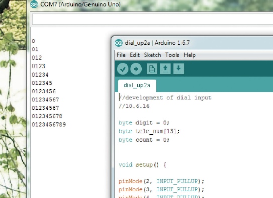
Left, shows the build up of output, on the serial monitor, from dialling zero to nine.
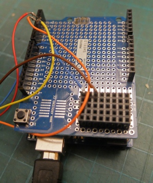
Above and left, output from the switches simply gets connected between an Arduino pin (via a proto shield) and ground (zero volts).
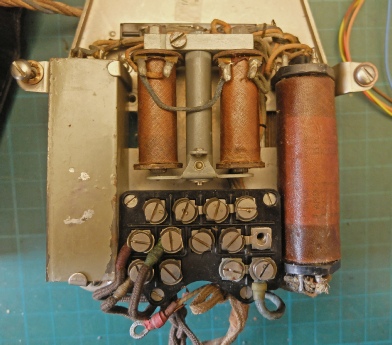
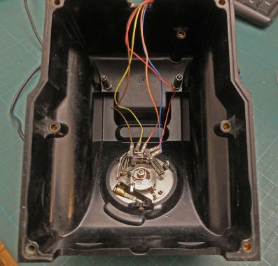
Left, some of the heavy duty inner workings of the model 332 telephone.
Capacitors (0.1 and 2 microFarads)
Bell mechanism (no bells or striker fitted)
“Induction coil” with three windings
Somewhere in there are two 30 Ohm resistors. On the other side of the chassis is the 2 pole switch operated by the hand set cradle.

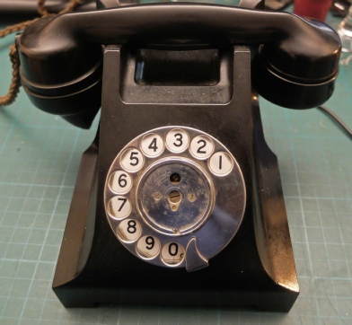
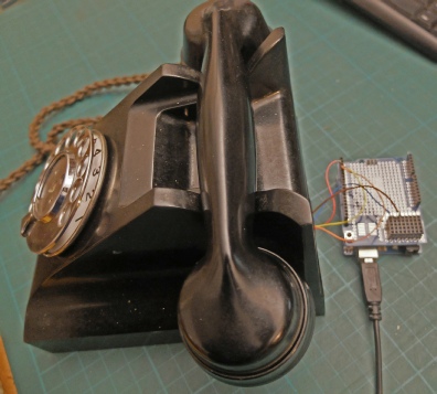
Model 332F phone that I rescued from a skip many years ago when the old Strowger PABX telephone system was being ripped out and being replace by an electronic system where I worked.
It’s a rather wonderful hunk of Bakelite! One thing that immediately strikes you is how heavy it is compared to many modern appliances of a similar size. It contains a sizeable quantity of steel in a chunky internal chassis and a lot of copper in magnetic windings of one type or another. It also looks like it could last forever!
The design dates back to the Swedish Ericsson company in the early 1930s and by 1937 was being mass produced by British companies. It is possible to make these phones work with current land lines with a bit of modification, apparently but my phone is missing a few bits and I am going to try to get it working with the mobile network with the help of an Arduino.
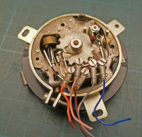
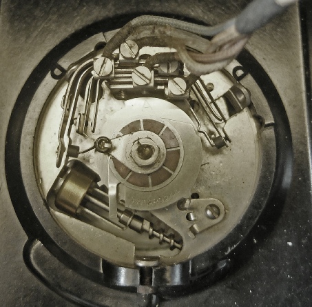
Above are two examples of perhaps the most important part of the phone, the dialling mechanism. The one on the right is from the 332 and the one on the left is a later version with a transparent plastic rather than a metal dial.
They work by tripping a switch as the dial is released and winds down. The number of pulses from the switch corresponds to the number dialled (zero has ten pulses). Another two-
A mechanism prevents the switch from producing pulses when it is being wound up. There is a difference here between the two mechanisms shown above (otherwise they are very similar).
A centrifugal brake governs the speed of the dial to produce pulses which are consistently spaced apart.
These are beautifully engineered mechanisms and are much more aesthetically pleasing (IMHO) than some push buttons real or simulated.
Centrifugal brake (governor)
Dial rest-
Pulse switch


Pulse switch
Centrifugal brake (governor)
More details of the old phone system here…