


 Home
Home

Under construction
From Feather to Zero
Previously I intended to use th Adafruit Feather to get my project wifi connected but I am now looking at the Raspberry Pi Zero to solve all my embedded mico-
You need a keyboard, mouse and monitor to set up the Zero initially but once you have wifi working, you can dispense with these and use VNC running on a PC (or even a tablet) to write, load and run programs. (Running headless). Running headless you might need to force the video into a bigger than default format to see everything you’ve programmed into the Tkinter window. To do this config.txt has to be edited. In Terminal enter:
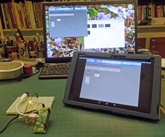
Left shows a program running on a Zero to control the brightness of some LEDs using pwm. (This is, I think software pwm which, perhaps, explains the flickering apparent on low value duty cycles -
The program is in Python with a Tkinter GUI. There are an option list and a slider widgets to control the pwm value (and some buttons which turn some GPIO pins on and off).
The software for this can be found here.
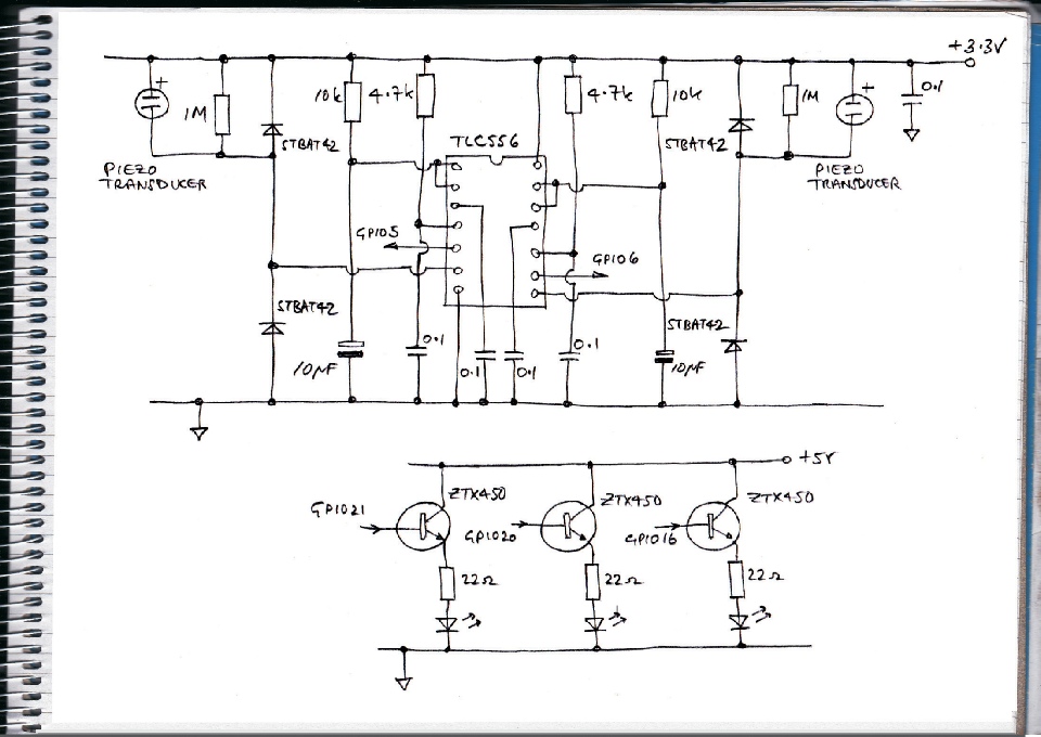
The circuit uses a dual 555 timer (TLC556CN) so I can use two sensors (one for the knocker and one to detect a knock on the grass door). The output from the sensor is enough not to need amplification (although the glass door sensor might, I haven’t tested that yet). A couple of diodes clip any over-
USB wifi dongle on adapter lead

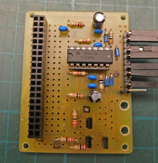
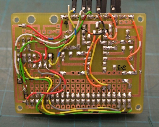
I designed a pcb to accommodate the dual 555 timer (TLC556CN) and the 40-
The three transistors drive the LEDs with enough current to make them shine brightly. I would normally put the LEDs in the collector circircuit but I had already wired the cathodes together and didn’t want to take things apart. The disadvantage of using an emitter follower circuit is that the transistors are not in their very low resistance state and will be dissipating power in the form of heat which would not be good for a battery powered circuit. The circuit will be mains popwered so it is not a real issue here.
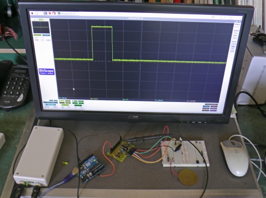
This trace shows the sort of output the GPIOs will see -
Uno kindly providing 3.3 volts to power the circuit!

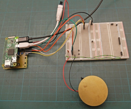
Pi Zero plugged into circuit.

Ready for testing with the Pi Zero running the Python with Tkinter GUI test/control program
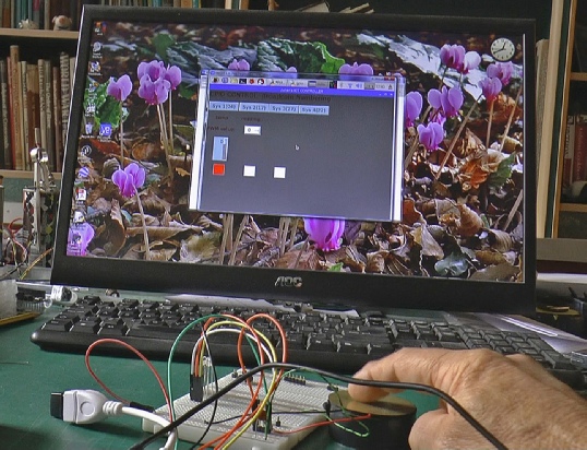
When the piezo is tapped, the software turns this button red.

Real VPN showing the Pi Zero desktop running the Tkinter GUI monitoring the GPIOs.


Piezo-

Pi Zero and circuit out of shot.
Next, a case for the Zero and pcb
sudo nano /boot/config.txt
Set the following:
hdmi_force_hotplug=1
hdmi_group=2
hdmi_mode=9
hdmi_ignore_edid=0xa5000080
F3 to save, F3 to quit, then sudo reboot. Mode 2 gives 800 x 600 which is enough for my application but bigger sizes can be used. (See RPi documentation).