

 Home
Home

Under construction
Constructing the doorbell (or door knocker)
For the construction, to make life simpler (I hoped), I started off with a cheap door knocker from Screwfix. (I could substitute the “knocking” part for something more interesting later (if I ever get round to it!) First I drilled out the pivot so I could dismantle the knocker. Eventually I will replace the rivet with a stainless steel screw and domed nut.
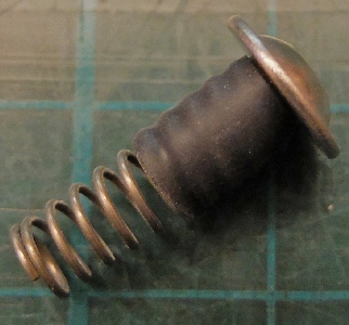
To communicate the blow from the knocker to the piezo I felt I needed to incorporate a spring to reduce force on the sensor which could be damaged, perhaps, by over-
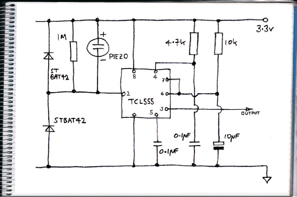
This is the final circuit without transistor amplification. I thought I ought to try to clamp the piezo’s voltage with the diodes as several volts can be generated. The 1M resistor discharges the charge generated when the piezo is deflected which remains until the deflection is released. The TCL555 has very high input impedances and without the resistor, the trigger terminal could remain low for around a minute which will keep the output terminal high. If you wanted the piezo to act like a push button, this might be a useful property.
If the resistor is reduced to , say, 100k, pushing the sensor (with a finger) no longer triggers the 555. I assume this is because the deflection is too slow and the charge is bled away before it can reach the triggering level. A tap will still trigger it. I assume because of its speed.
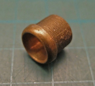
Brass ferrule
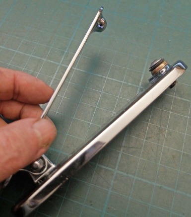
Screw with spring fixed using adhesive lined heat shrink tubing.
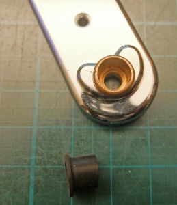
Knocker base drilled and ferrule pressed in. Below, the grommet cut down ready to fit into the ferrule.
Screw/spring combo.
Grommet.
Small a piece of shrink-


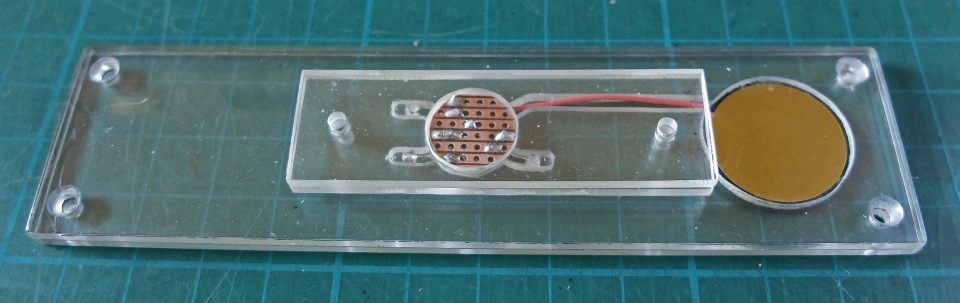
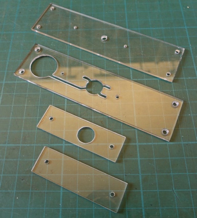
The knocker is going to sit on a base made of several layers of 3mm Perspex. The base will accommodate the piezo transducer, some decorative LEDs (which will light up the Perspex edge) and the connections to the electrical cable.
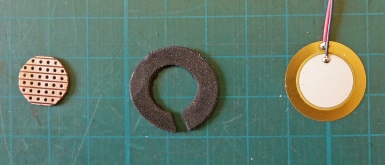
This pic shows a small piece of strip board (Veroboard), a foam ring which fits under the piezo transducer and the transducer itself.
Fixing holes (to the door frame).
These holes are tapped to M3 to secure all the parts together.


Piezo fits in here.
Connections made here.
LED goes here.
This is how the stack of Perspex bits, the sensor, the LEDs and the strip board fit together.