 Home
Home


The program checks overload conditions. With a mild overload, the program attempts to park the wipers and waits for the stalk to be turned to “off” to reset. With a heavy overload the wipers stop wherever they are until reset as above. It is important to measure average current rather than take a single instantaneous value (although I beak my rule for extra-
The system measures the position of a six way switch. Position 1 is normal ie. Off, slow, fast, single from the stalk. Positions 2 – 5 give delayed action on stalk set to slow. Off and fast over ride these.
Position 6 is an experimental auto position whereby the wipers run at slow until current measurement detects a drying screen when a five second delay is introduced. Further drying causes the wipers to be parked until reset as above. The “drying” current value is set by the parameter potentiometer.
Download a PDF of the program here…
Control software & construction details
Software
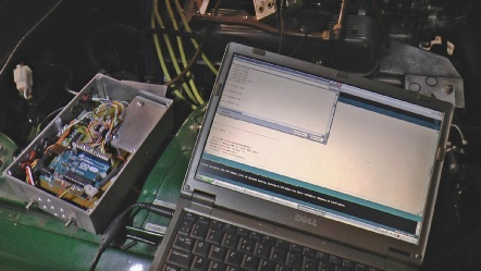
Testing the system on the car
Construction
Construction
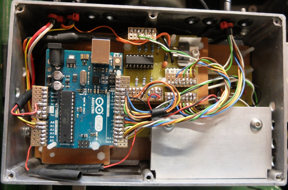
The circuit is built on two circuit boards plus the Arduino. The PCB at the bottom, which is difficult to see in the picture above, has the motor control mosfet, the driver chip and the over voltage generation and current measurement circuitry etc. It takes up much more space then necessary as I had been trying to construct a “universal” motor controller PCB with room for an Adafruit Trinket and other bits and bobs. As it turned out I needed an Arduino as the Trinket didn’t have enough ins and outs so that space on the PCB was not used and there were other features I had expected would be “universal” but weren’t.
The other PCB contains the opto-
The aluminium plate bottom right in the picture above is bolted to a piece of angle which forms the heatsink for the mosfet and regulators. The size of this is probably over the top but better to be safe than sorry etc. etc.
There is a piece of thin Tufnol in the bottom of the box and the PCBs are attached to that with nylon nuts and bolts. All this is to ensure that nothing can short circuit to the metal of the box.
To connect to the motor, I was able to buy a Lucas style windscreen wiper motor plug here. I used a couple of male blade connectors to tap into the original plug. These provide the signals to the Arduino which relate to the position of the stalk switch. It is, therefore, possible to revert to the original system just by replacing the original plug in the motor socket.
Testing
Testing involved running the windscreen wipers with varying amounts of water sprayed on the screen to simulate various conditions of rain. With the Arduino connected to a laptop, various parameters could be altered in the program and downloaded for testing.
The main areas for adjustment are the current monitoring and response. Given that the current drawn is constantly varying as resistance to the motion of the blades varies as they sweep across the screen, some sort of averaging process is required. I have tried a couple of methods. One is to measure the current every such and such fractions of a second for such and such a period and take an average. If the average exceeds some specified value, that means an overload. Another method is to think of a (high) value of current a count how many times that is exceeded in a certain period of time. When a threshold is crossed, an overload condition is inferred. Also, if an absolute instantaneous value is exceeded then that could trigger an overload condition.
The way I have played it in my program is that following an overload triggered by one of the averaging methods, the system goes to “park”. If the absolute maximum threshold is crossed, the mot just stops wherever it is. So there are lots of parameters to play with.
The program also has to ignore the startup current which is always high.