
 Home
Home


V8 cooling
The cooling is carried out by means of a Davies-
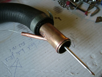
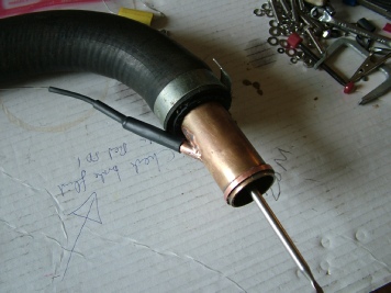
The radiator is cooled by an electric fan from a Rover two litre turbo engine. There is no mechanical fan powered by the engine. The fan is switched on and off by a capillary style thermostat. The sensor is located in the bottom hose, the cold outlet from the radiator. This means that the engine receives water at a more or less constant temperature which is how I think things should be.
I like capillary temperature sensors as I believe they are pretty reliable compared to electronics and they don’t need electricity to work. (I like capillary water temperature gauges for this reason.)
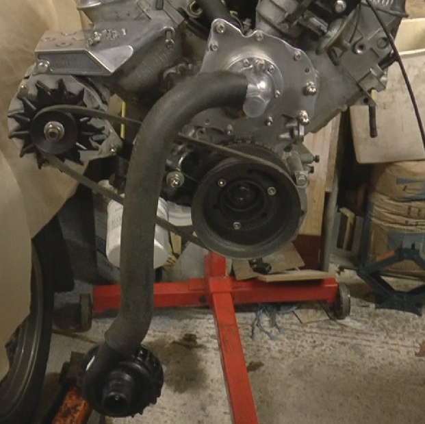
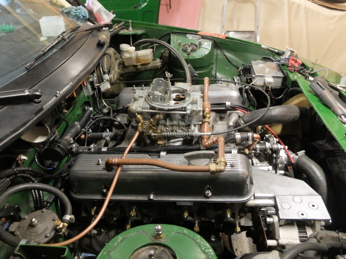
The original pump has been replaced by a blanking plate fitted with a hose outlet from a Rover T-
Pump blanking plate
Short belt (no pump pulley)
Davies-


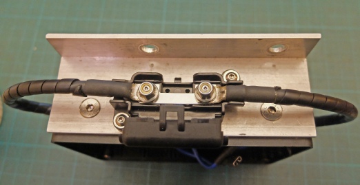
The sensor for the electric fan fits in the engine bottom hose, following the pump. In the pictures below, copper tube has small tube silver-
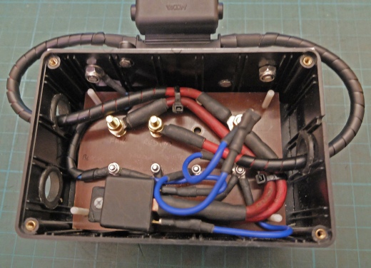
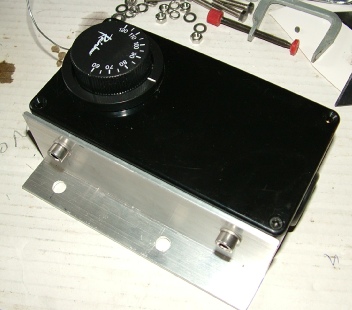
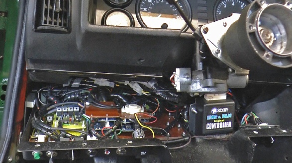
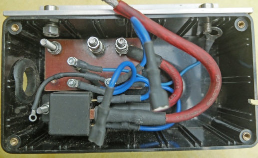
The thermostatic switch and 40 amp relay fit in box with a 30 amp strip fuse. It needs a heavy duty supply preferably direct from the battery.
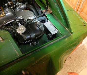
Switch/relay unit

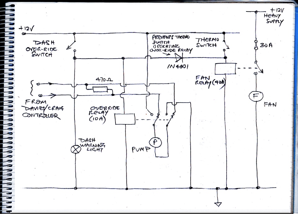
Later, I developed the circuit (see below) to include a feature whereby the actions of the pump controller and the fan thermo switch could be over-
The circuit uses a relay to switch the pump from the controller to a plain 12 volt supply. A diode prevents normal operation of the thermo switch from triggering the over-
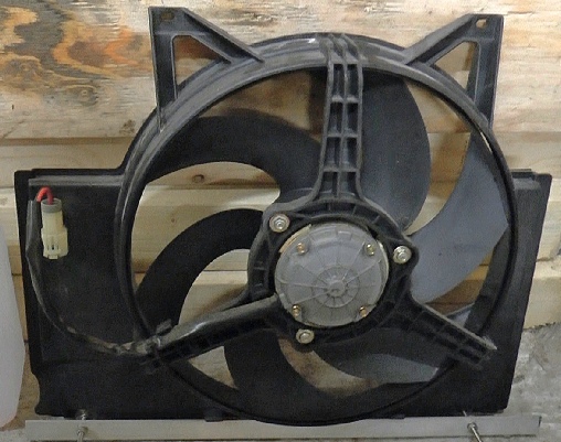
Rover 820 Turbo Vitesse Sport electric fan. If current consumption is anything to go by (it might not be!) this is one heck of a powerful fan.
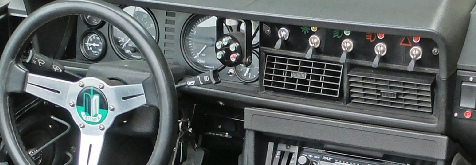
Switch on dash turns on both radiator fan and water pump for very rapid cooling (as long as there’s still coolant left in the system! -

See picture left. The Davies-
(I didn’t intend for all this stuff to get so complicated, it just happened, officer.
The truth probably is it’s more pleasant to do electrical stuff on a bench than to crawl under the car and get greasy! It’s a sort of displacement activity.)
Since the Davies-
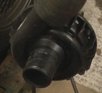
Small heater pump


Later it occurred to me that the Davies-
In implementing this circuit, my first attempt attempt failed after about a 1000 miles! I had a strip fuse clamped between two bolts acting as terminals for the heavy cable that the fan needs. The nuts must have loosened and the terminals overheated, eventually causing the fuse to fracture (rather than blow). Fortunately, the Davies-
Heat damage to 5 mm tufnol terminal block.

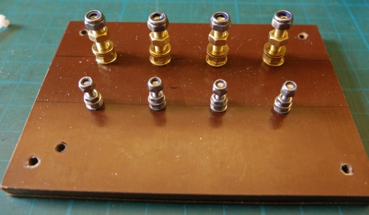
I made a new base for a new terminal block out of tufnol and used M5 brass screws for the high amperage terminals. Brass conducts electricity better than the stainless steel I had used previously so there wont be as much potential for the joints to heat up unless the nuts loosen. That’s where the extra nyloc nuts come in.
I’ve also made the whole thing bigger and fitted it into a bigger box so that the wiring won’t be so squashed which should reduce the risk of heat build up and short circuits.
This time I’ve put the strip fuse in a purpose made holder on the outside of the terminal box for better access.
It should be an improvement, hopefully.
These connectors plug into the thermo-

See here for an alternative to the electro-
on the mechanical fan thermostat described on this page below can be seen here.
NB: An improvement (I hope!)