 Home
Home


Trigger wheel and VR sensor setup 1
I have fitted Megajolt ignition on three different Rover V8s all in slightly different ways. The first shown is on my white SD1 which is the least “engineered”. The second is on my Rover P6 which is over-
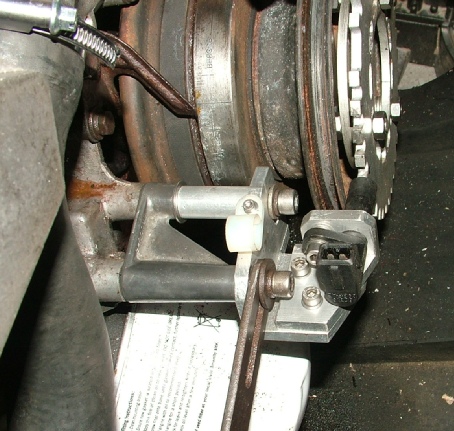
Fortunately, there are plenty of bolts around the front pulley where a bracket for the VR sensor can be fitted. Unless you plan reasonably carefully or are lucky, a little bit of adjustment for the sensor round the circumference of the trigger wheel is needed as the slotted adjustment in the trigger wheel itself has its limits. So the VR sensor needs to be approximately in the right place with the locking bolts in the middle of one of the trigger wheel slots. (Even if the sensor can’t be got in exactly the right place, in truth, it’s possible just to add or subtract a few degrees in the software.)
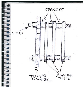
The SD1 installation is shown below. The trigger wheel is bolted to the front of the pulley on long studs which are reinforced by a succession of spacers (available from www.trigger-
The VR sensor is under the alternator and the bracket does make tightening the alternator stay awkward. However, the bracket could easily be redesigned to make things easier.
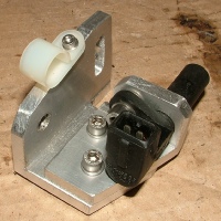
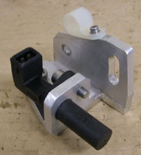
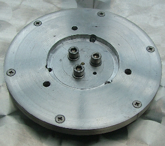
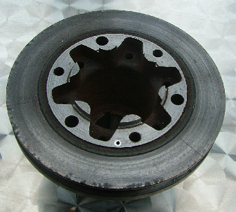
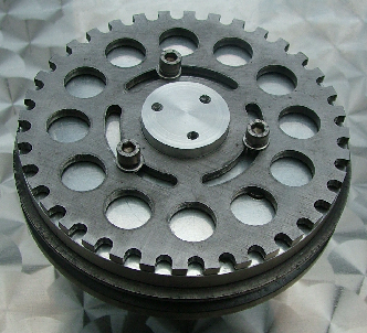
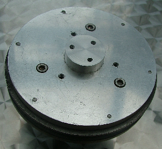
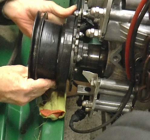
My P6 installation is shown left. The original pulley was worked on on a lathe to produce a locating flange (picture 1). Two aluminium discs were cut and screwed together. One had a hole cut on the lathe to fit closely over the locating flange on the pulley previously mentioned. The other had a short stub of aluminium bar screwed to it to closely fit the central hole in the trigger wheel (pictures 3,2). (The assembly could have been made in one piece if I had had a lump of aluminium big enough but there would have been a lot of work on the lathe.)
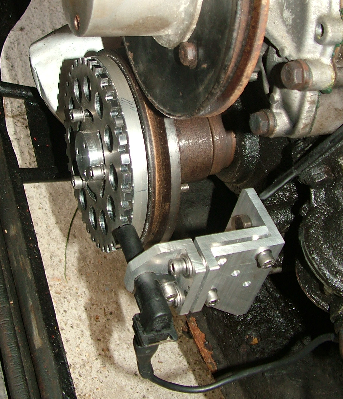
The whole lot was bolted together and the trigger wheel teeth were trued up on the lathe. (Picture 4) I think I was expecting to have to get the VR sensor to within a fraction of a millimeter of the teeth of the wheel. However, it’s not that critical and about a millimeter will do.
1
2
3
4
The bracket for the VR sensor allows adjustment in all directions.
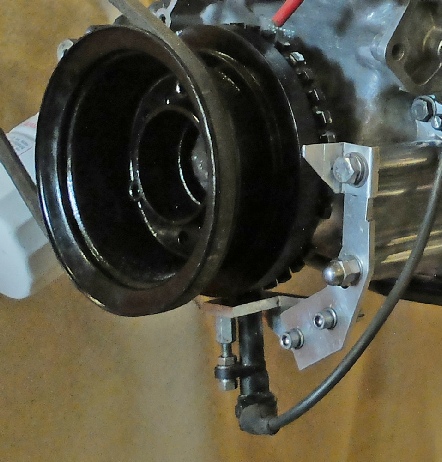
The TR7 installation is shown below. I can’t quite remember after several years exactly why I made it exactly like this (getting old)! Anyway, I did draw it up using CAD so that the slots (which are difficult to see under the fixing bolts to the engine) are curved correctly to move the sensor round the wheel without changing its distance from the teeth (much). The trigger wheel is mounted at the back of the pulley which has the oil catcher (I think that’s what it is) removed to allow this to happen. This means the wheel can’t be adjusted once it is in place so I rely on the VR adjustment (and the efficiency of the front oil seal!)
I have fitted a pointer and engraved new TDC and 10 degrees before and after which are easier to see. (These can’t be seen in these photos.)
More details of the setup follow…