
 Home
Home


Under construction
Temperature sensor
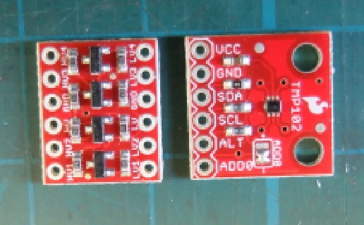
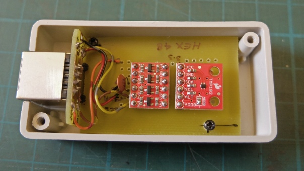
The sensor uses the TMP102 sensor in a breakout board by Sparkfun (purchased from Pimoroni) and, since the sensor works at 3.3 volts and my Arduino at 5 volts, a logic level converter also from Sparkfun.
The TMP102 transmits data through I2C which, I understand is meant to transmit data within a piece of equipment rather than over a long cable. However, in tests it seems to work over about 9 metres. I use flat RJ45 to connect. This goes under carpets and suchlike and is cheap considering it comes with terminating plugs.
Considering how small the boards are (about 15 mm square) it should be possible to make the sensor really tiny. The logic level converter could be in the timer itself to make it even smaller. (However, would the lower voltage reduce the cable length that could be used?). My overall unit is not as small as it could be -
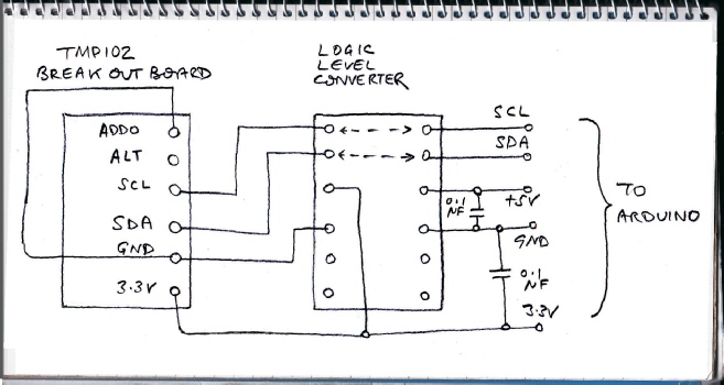
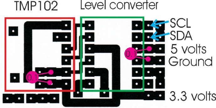
This is the circuit diagram (left). The ADD0 connection on the TMP102 needs to be tied to 3.3 volts for an I2C address of 72 (48 hex) or to ground for an address of 73 (49 hex). This suggests you can only use two sensors in the system.
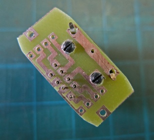
Small PCB is needed to connect to the RJ45 socket
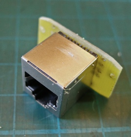
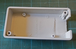
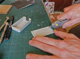
The socket only just fits into this Hammond 1551K box. It needs to be thinned by scraping with a Stanley knife to make room.
Another PCB will be needed to connect the TMP102 to the logic level converter. A piece of strip board could be used although it should be noted that the connections are not just straight across from hole to hole.
This is the PCB layout.
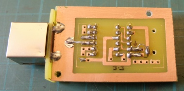
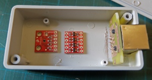
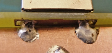
I’ve joined the two PCBs by bridging with two blobs of solder between the tabs on the RJ45 socket and the PCB. A bead of epoxy would probably also help to secure the two together.
(You can make all sorts of structures by soldering pieces of PCB together, for example, small boxes. The strength depends on how strongly the copper is bonded to the substrate.)
Here the assembly is screwed into the box. It still needs some wall-
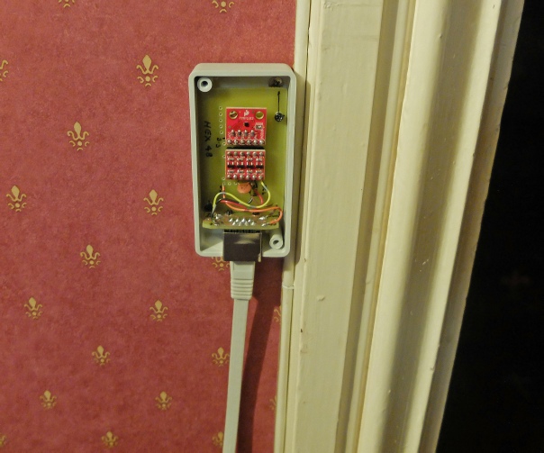
Installed on the wall (minus its cover). The I2C does not seem to have any difficulty transmitting 9 metres. Just need to glue the cable to the wall or woodwork with a little contact adhesive.