

 Home
Home

Radiator fan circuit
//fan test 1
//2.3.16
int pwmPin = 1;
int timing = 10000;
void setup() {
pinMode(pwmPin, OUTPUT);
analogWrite(pwmPin, 0);
}
void loop() {
analogWrite(pwmPin, 100);
delay(timing);
analogWrite(pwmPin, 255);
delay(timing);
analogWrite(pwmPin, 100);
delay(timing);
analogWrite(pwmPin, 0);
delay(timing);
}
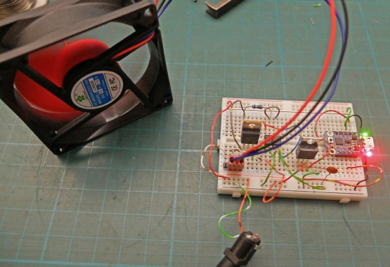
The basic circuit to control the fans is constructed on a bread board
The is the initial test program which cycles the fan between slow, fast and off.
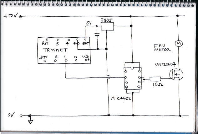
This is the stage one test circuit. The Adafruit Trinket gets 5 volts from the 7805 connected to the Bat terminal. This is reduced internally to the 3.3 volts the Trinket needs. I include the external regulator as I feel it is a lot to ask the tiny on board regulator to drop all the voltage (even though the specs say it can!)
Pin 1 (which is pwm capable) is connected to the MIC4422 driver IC for the mosfet.
//fan test 3. 4.3.16 tests temp102
// credit Arduino Playground author for temp102 routine
#include <Wire.h>
#define TMP102_I2C_ADDRESS 0x48 // I2C address TMP102 A0 to GND (0x48 = 72 = 1001000 for GND, 73 for vcc)
int pwmPin = 1;
//////////////////////////////////////////////////////
void setup() {
pinMode(pwmPin, OUTPUT);
analogWrite(pwmPin, 0);
Wire.begin();
}
////////////////////////////////////////////////////////////////////////////
// function to read temperature
int getTemp102(){
byte firstbyte, secondbyte; //these are the bytes we read from the TMP102 temperature registers
int val;
float convertedtemp; /* Then multiply the two bytes by a scaling factor, mentioned in the datasheet. */
/* Reset the register pointer (by default it is ready to read temperatures)
You can alter it to a writeable register and alter some of the configuration -
the sensor is capable of alerting you if the temperature is above or below a specified threshold. */
Wire.beginTransmission(TMP102_I2C_ADDRESS); // start talking to sensor
Wire.write(0x00);
Wire.endTransmission();
Wire.requestFrom(TMP102_I2C_ADDRESS, 2);
Wire.endTransmission();
firstbyte = (Wire.read());
/*read the TMP102 datasheet -
each of the temperature registers on the TMP102*/
secondbyte = (Wire.read());
/*The first byte contains the most significant bits, and
the second the less significant */
val = firstbyte;
if ((firstbyte & 0x80) > 0) {
val |= 0x0F00;
}
val <<= 4;
/* MSB */
val |= (secondbyte >> 4);
// LSB is ORed into the second 4 bits of our byte.
convertedtemp = val*0.625; // temp x 10
int temp = (int)convertedtemp;
return temp;
}
/////////////////////////////////////////////////////////////////////////////////////
void loop() {
int tempNow = getTemp102();
if(tempNow < 180) {
analogWrite(pwmPin , 255);
}
else {
analogWrite(pwmPin, 0);
}
delay( 1000);
}


Under construction

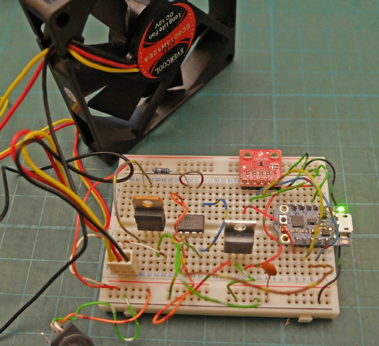
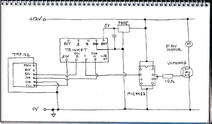
Next in line is to test the Trinket with the Sparkfun TMP102 I2C temperature sensor break out board.
The program below reads the temperature and if it is less than 18 degrees Celsius it turns on the fan.
Trinket
7805 regulator
MIC4422 driver
VNP20N07 mosfet


TMP102 on break out board

Some more software and circuit details next…