 Home
Home


Under construction

Phone final design part 1
The Arduino Uno will almost certainly not have enough memory for the things I might want to do with the system. (I haven’t worked out exactly what that might be and how I could get it going at this stage but I am trying to keep my options open.)
I have been trying to avoid devices such as LCD screens or LEDs to retain the vintage feel of the phone. Instead, I am hoping to use audio cues to indicate the status of the system, for example, a dialling tone to indicate whether the FONA is connected to a network when the handset is picked up off the cradle.
I shall be using the Arduino Mega with its much bigger memory and many more pins etc. For the audio side, I am using the Adafruit Music Maker. This also has an interface for an SD card.
The SD card can store pre-
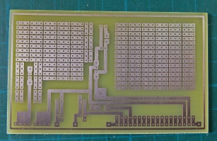
Left: this is the pcb I have made which provides a place to plug the FONA in and the 3.7 to 5 volt step-
FONA
Step-
Adafruit Music Maker
Arduino Mega
Speakers
Vintage 5-


Below -
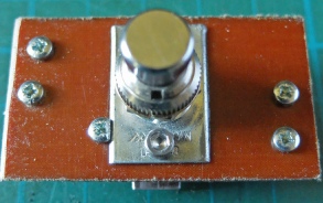
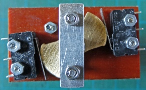
Left: this is a rotary on/off switch I have made using an old foot switch similar to the one I used to make the call switch. The idea is to give it a vintage look and feel. Two micro switches balances the switch action although only one is used from an electrical point of view. I was able to press a 4mm aluminium riv-
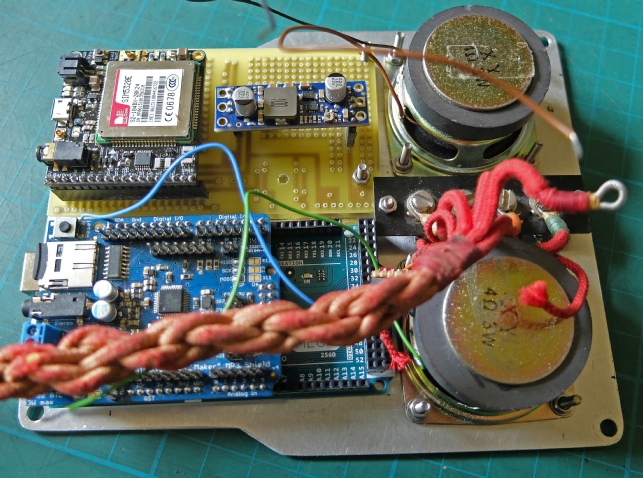
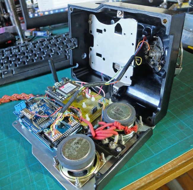
Left: most of the wiring completed on the phone. The reset switch for the Mega (the button will be underneath the base) and the LEDs (underneath so you just see a slight glow when the phone is on) have yet to be fitted in this picture.
I also need to find some suitable rubber feet to lift the phone up enough for the sound to get out.
Battery is under this pcb.
DIL relay controls resistor in series with handset speaker to reduce the volume (this could be too loud even at the lowest volume set by software).


Below: initial placing of the main components on the base
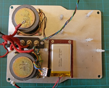
After trialling the various bits, I found I could fit the battery under the pcb. A bit of tufnol holds it in place with a couple of cheese-
By the way, nylon screws are good for fixing things (if you only need minimal torque) as (obviously) they don’t conduct electricity and they don’t loosen with vibration.
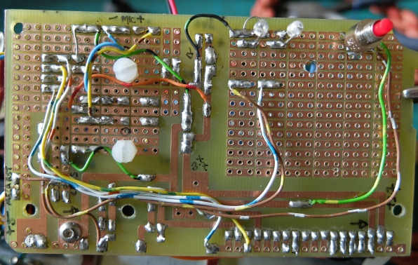
The prototyping area has indeed come in handy for making various connections that I found I needed as I went along!
Status LEDs. One for power, one to show if the phone is registered on the network
Reset switch for the Arduino Mega.

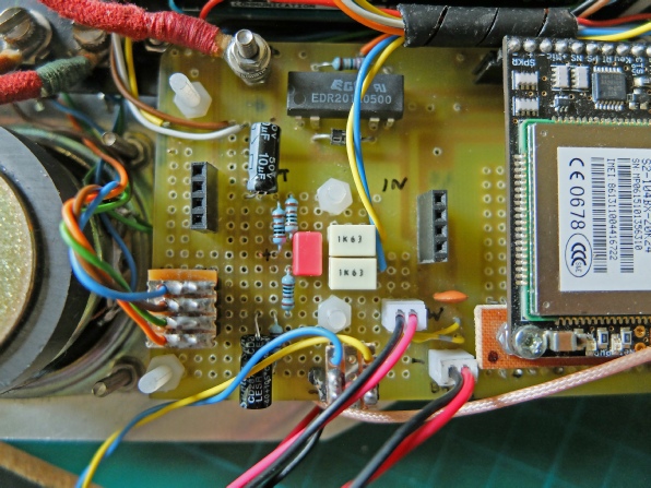
The latest additions to the prototyping area are the components needed to power and filter the supply for the electret microphone which I have fitted to allow audio recording on the Adafruit Music Maker. (See here -
Exactly how I can use this remains to be seen!.