
 Home
Home


Under construction
Phone final design part 3
Noise filtering
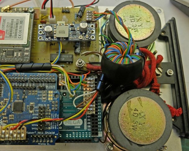
In an attempt to reduce noise pickup, I have wound the wires from the microphone and speaker around and through ferrite torroids and soldered in shunt capacitors to produce a totally undesigned low-
The circuit diagram is shown below. It has improved matters but in certain positions, noise pickup is apparent to the party on the receiving end of a call from the old phone. More work may be needed!

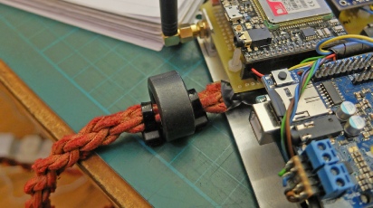
Ferrite torroid.
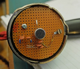
100nF capacitors


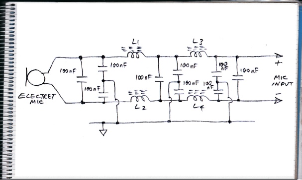
This is roughly the equivalent circuit. The speaker filtering is the same. However, the inductances are all coupled and that must make a difference. Also I have wound the leads in the same direction round the torroids which I hope is the right thing to do!
Eventually, I became a bit more systematic about testing different microphones. This video shows how different microphones can pick up widely different amounts of interference.
As the video shows, one microphone, removed from a £2.99 headset performed very much better than all the others. Why this should be, I just don’t know.
I substituted this microphone into the old phone’s handset and I was at first disappointed. I then removed the microphone lead in the main body of the phone from the ferrite toroid it had shared with the speaker lead. This solved the problem and the interference subsided. The microphone needed amplification and the AT command AT+CMICAMP=1 fixed that.
I am left with more low level white noise than I feel I would normally experience from a cell phone but, overall, I think I can call that a result!