Development of the software and final testing
 Home
Home


//test for security light
//16/2/16
//NB HIGH & LOW reversed for test beacause of breadboard connections
#include "Wire.h"
#define DS3231_I2C_ADDRESS 0x68
// Convert normal decimal numbers to binary coded decimal
byte second, minute, hour, dayOfWeek, dayOfMonth, month, year;
byte result;
int initialon = 10; //time light on in minutes when initialy switched on before going into timed mode
byte maxmins = 15; //maximum random delay in minutes
//on off times in minutes for each of te twelve months of the year (all in GMT -
int morningOn[] = {0,450,450,450,450,450,450,450,450,450,450,450,450};
int morningOff[] = {0,570,570,570,570,570,570,570,570,570,570,570,570};
int eveningOn[] = {0,1140,1140,1140,1140,1140,1140,1140,1140,1140,1140,1140,1140};
int eveningOff[] = {0,1380,1380,1380,1380,1380,1380,1380,1380,1380,1380,1380,1380};
int mornOn, mornOff, evenOn, evenOff;
boolean ison = false; // two flags needed to signal when light just tuned on or off
boolean isoff = true; // to prevent random delay to on and off being constantly applied
long randnum;
// Convert binary coded decimal to normal decimal numbers
byte bcdToDec(byte val)
{
return( (val/16*10) + (val%16) );
}
void setup()
{
Wire.begin();
pinMode(4, OUTPUT);
digitalWrite(4,HIGH); //light on for initial period when first turned on
delay(initialon * 60000);
digitalWrite(4,LOW); //light off
}
//routine to get time from clock
void readDS3231time(byte *second,
byte *minute,
byte *hour,
byte *dayOfWeek,
byte *dayOfMonth,
byte *month,
byte *year)
{
Wire.beginTransmission(DS3231_I2C_ADDRESS);
Wire.write(0); // set DS3231 register pointer to 00h
Wire.endTransmission();
Wire.requestFrom(DS3231_I2C_ADDRESS, 7);
// request seven bytes of data from DS3231 starting from register 00h
*second = bcdToDec(Wire.read() & 0x7f);
*minute = bcdToDec(Wire.read());
*hour = bcdToDec(Wire.read() & 0x3f);
*dayOfWeek = bcdToDec(Wire.read());
*dayOfMonth = bcdToDec(Wire.read());
*month = bcdToDec(Wire.read());
*year = bcdToDec(Wire.read());
}
void loop()
{
readDS3231time(&second, &minute, &hour, &dayOfWeek, &dayOfMonth, &month,
&year);
mornOn = morningOn[month];
mornOff = morningOff[month];
evenOn = eveningOn[month];
evenOff = eveningOff[month];
int timeNow = hour * 60 + minute; // get current time in minutes
if((timeNow >= mornOn && timeNow < mornOff) || (timeNow >= evenOn && timeNow < evenOff)) { // check if time is "right"
isoff = false;
}
else{
isoff = true;
}
if(ison == false && isoff == false) {
randnum = random(15)*60000;
delay(randnum);
digitalWrite(4, HIGH); // light on
ison = true;
}
if(ison == true && isoff == true) {
randnum = random(15)*60000;
delay(randnum);
digitalWrite(4, LOW); //light off
ison = false;
}
}
This is the final program. The times in the arrays are the on/off times, in minutes, morning and evening, for the lights. There is potential for different times for each month to adjust for the difference in daylight. (NB the clock does not correct for Summertime so all times should be in GMT.)
The software needs to delay the turn on and the turn off for (pseudo) random times to give the system more verisimilitude. This caused my poor old ageing brain a bit of trouble. The problem is to restrict the random time delays to just before the light is turned on and before it’s turned off. After a bit it occurred to me that there were four states for the system, light off, delay before light turns on, delay before light turns off and light off. One way to organise that would be to use two boolean flags which gives four possibilities, true-
So lights off is represented by false-
The on time when power is first applied (so that the light will turn on “out of hours”) is set by initialon and the maximum on/off delay is set by maxmins. With a preset potentiometer connected to pin 3, one of these could be adjusted. (If the connection to the transistor/relay were rearranged to pin 1, then another analog pin would be freed up for another potentiometer. (Pins 3 and 4 are analog, pin 2 is also analog but is used here as SCL for the I2C connection to the clock.)
Finally, some possible extras…
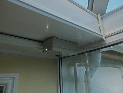
Above, the unit screwed to some lovely UPVC.
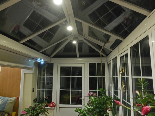
Right, two of the four LED spots controlled by the unit in the conservatory.