 Home
Home


Megajolt part 2
The Megajolt needs two separately fused power supplies. One for the Megajolt electronics and one for the EDIS unit which triggers the coil packs. These need to be on with ignition. I describe below some points connected with providing the power. In this case I wanted to connect up other circuits as well so the circuit turned into a general purpose power distribution board. It does not have to be so complicated! (See my SD1 installation.) In all cases, I have fitted the circuitry in a glove compartment. The EDIS unit, however, can go in the engine compartment.
My first step when I am fitting something electrical into an old car is to secure a good quality power supply. By this I mean a connection to the car’s battery that can supply sufficient current without the cable or any connectors that may be present having enough electrical resistance to drop voltage and generate heat. Ohm’s law states that the voltage across a circuit is given by V=IxR. So significant voltage can be lost in any circuit which has anything but the tiniest resistance. Also power dissipation (in the form of heat unless the circuit starts to glow) is given by P=IxIxR. So the aim is minimal resistance. The resistance can be found in connectors or switch contacts which are too small or dirty or oxidised by previous high current events. Cable has resistance, the thinner the cable the higher the resistance which is why thicker cable is needed to cope with higher current.
On a metal car, the body or chassis provides one connection to the battery and normally can be considered to have an extremely low resistance. The same cannot always be said about the connection to the chassis. Dirt or rust can cause a high resistance or even an open circuit. If several different circuits are connected to this same point, current from one circuit can flow into another circuit with unexpected results. If a high current circuit and a low current circuit share the same chassis connection and the connection has significant resistance, then a voltage drop proportional to the current in the circuit will occur and that will feed back into the other circuit, again, with unpredictable results.
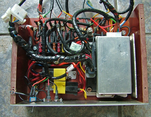
So, to return to the power supply for my Megajolt, It involves a 50 amp cable from the battery and a 50 amp cable to the chassis. (Should there be a 50A fuse at the point where the cable connects to the battery? This would protect from a short circuit caused by cable damage.) I mount my supply on a piece of 6mm Tufnol. I drill and holes for M6 counter-
I then provide one or two 40A relays to provide a supply which is on with the accessory position on the ignition switch and another which is on with ignition. These are supplied direct from the ignition switch or any handy existing circuit nearby. I then fit a bank of say 8 blade fuses and divide them up between the always on, on with accessory, and on with ignition supplies. This way I have independent supplies for the Megajolt and spare supplies for other circuits or the gradual re-
Of course, you don’t have to go to all this trouble. You could just tap into existing circuits or produce a more limited supply circuit as I did on my SD1 Megajolt installation (see below).
More circuit details next…
Power supply -
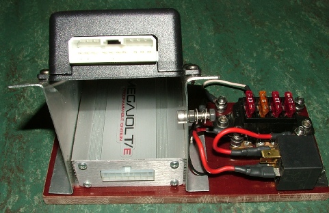
Modern Megajolt is tiny!
SD1 installation
Rover P6 installation
TR7 installation
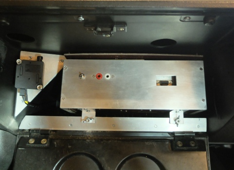
Megajolt electronics
EDIS unit
EDIS is in engine compartment in this case.
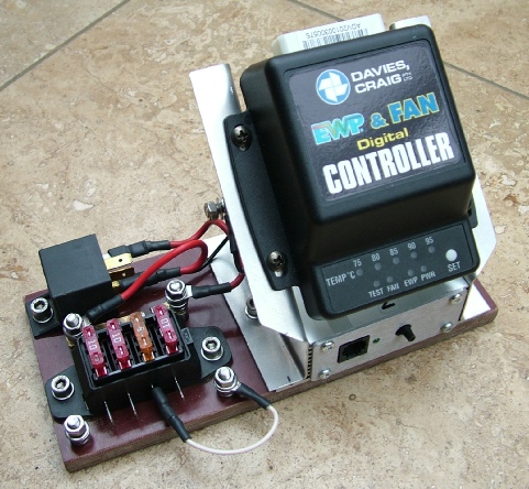
EDIS is in the engine compartment in this case also. Unit also has Davies-
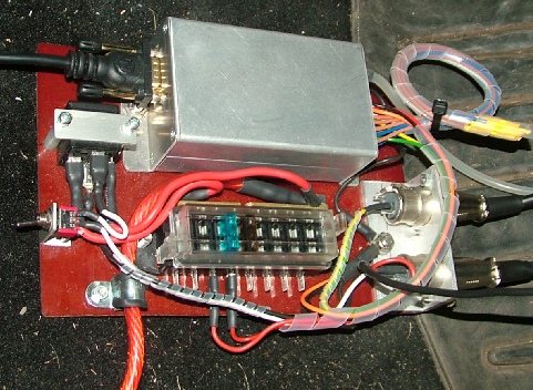
Relays to switch “on with accessory” and “on with ignition”
Chassis terminal
Terminal for 12volt supply from battery


MAPS inlet manifold vacuum sensor tube connects here
Programming socket
Socket for power,EDIS, trigger wheel sensor etc.


Switch to select alternate ignition map

Inertia switch (from an SD1). Turns off ignition in a crash.
Programming socket
Map select switch
Power socket

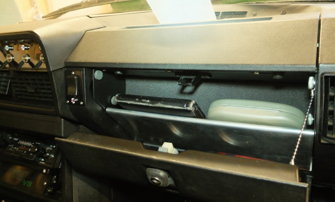
In the TR7, the Megajolt and power distribution board takes up most of the glove compartment.
However, my cover plate includes enough storage space for a phablet and a pair of Ray Bans