


 Home
Home

Under construction
Improved headlight control construction and software
Speed setting
Switch motors
Push to test

Bi metallic overload trips

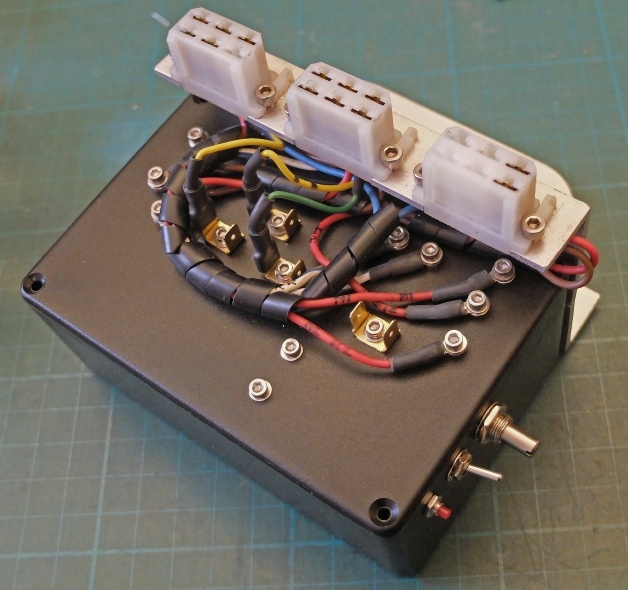
The circuit is housed in a plastic box similar to the previous unit. This is a bit of a crummy item made out of thin ABS. It looks like it would soften easily under heat and uses self-
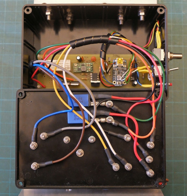
The terminals on the front reflect the way I connected the pcb for the previous unit where the terminals linked directly to pads on the pcb. Rather than rationalise the wiring (which has developed in a rather unplanned manner over the years and grown like Topsy) I have kept the arrangement.
These connectors use 6 mm brass spades and are cheap but bulky. They need to be used with care as the have no clip to retain them. I always solder the connections and use adhesive lined shrink tubing to reinforce and insulate the connection where I can.
The TO220 items don’t need heatsinks as the load only lasts a few seconds. (The pwm MOSFET only gets warm at the absolute slowest speed after 30 seconds or so.)
I have retained the bi-
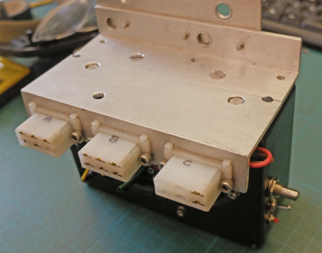
The unit bolts to the front bulkhead of the car using the bolts which hold the headlamp mechanism in place.
The headlamp MOSFETS and fuse unit screws to the top of this plate.


// trinket prog to run tr7 headlamp motors
// 5.1.17
// headlamp2
// gets trigger when lights are switched on (including flash)
// raises lights for at least 4 seconds to avoid retraction during flash
// slows one motor to equalise speed
// pin 0 = pin driving relay via ZTX450
// pin 1 = pwm for headlamp motor
// pin 2 = input from 555 Schmitt
// pin 3 = no connection (can't use because of triggering during start up)
// pin 4 = read pot for motor speed setting
int pot_pin = 2;
int rel_pin = 0;
int pwm_pin = 1;
int inp_pin = 2;
int pot_value = 0;
int run_time = 0;
int val = 0;
void setup() {
pinMode(rel_pin, OUTPUT);
pinMode(inp_pin, INPUT);
pinMode(pwm_pin, OUTPUT);
digitalWrite(rel_pin, LOW);
}
void loop() {
pot_value = analogRead(pot_pin);
pot_value = map(pot_value, 0, 1023, 0, 100);
// pwm is inverted because of inverter type driver
analogWrite(pwm_pin, pot_value);
// try to eliminate accidental triggering
val = digitalRead(inp_pin);
if(val == HIGH);{
delay(200);
}
// still on? -
val = digitalRead(inp_pin);
if(val == HIGH){
digitalWrite(rel_pin, HIGH); // lamp up
// wait for 2 seconds without any triggering before lamp down
while(run_time < 10){
val = digitalRead(inp_pin);
if(val == LOW){
run_time++;
delay(200);
}
else{
run_time = 0;
}
}
}
digitalWrite(rel_pin, LOW); // lamp down
run_time = 0;
}
The software is pretty simple although this didn’t prevent me making an error which took me ages to correct.
For some reason I had put a semi-
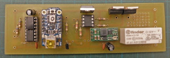
Opto isolators
Adafruit Trinket
Step up regulator
MOSFETS
MOSFET driver
SPDT relay
Schmitt trigger


