Home
Home
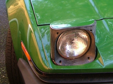
The first thing to do with the headlights is to replace the 7 inch sealed beam units which are hopeless with conventional bulbs. It’s very straightforward. I used Wipac Quadoptic units (only because I used them on the kit car I built many, many years ago).
When I bought the car the popup mechanism was not working and the car had to be driven with them permanently popped up! (I don’t think BL had too much faith in them as they proved a knob you could turn if you grovel on the ground to raise them manually.)
It turned out that the motors were functional and the mechanism was not in bad shape it was just the electrical control was shot.
I decided to replace as much of the electrical parts as possible and throw in some of my own stuff (keeps me off the streets!)
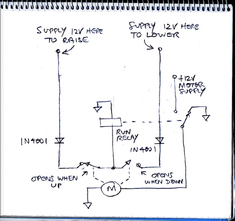
The motors operate the mechanism by means of a crank. The motor only turns in one direction which means that if it runs continuously, the light pods just go up and down continuously (which is quite a common fault condition apparently). Inside each motor and gearbox (they are slightly modified windscreen wiper motors, I think) there are two pairs of contacts which act as limit switches. One pair opens when the light is fully up, the other opens when it is fully down.
Each headlamp motor has a single-
12 volts can be switched to the relay in two ways, through each of the two limit switches respectively. When one of these receives 12 volts, the motor turns until it reaches a position where the limit switch opens which will be either completely up or completely down depending on which connection of the two has received 12 volts.
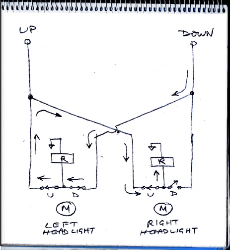
The diagram on the left explains why the diodes are present by showing what would happen if they weren’t there. The diagram shows two diode-
The other piece of circuitry in this system involves a device called the Pektron unit. This monitors the headlamp switch and dip/main switch and outputs the 12 volts to the up or the down connections to the run relay as appropriate.
Several circuits which could replace the Pektron unit are described on the next page.
Headlights