


Under Construction
Greenhouse lighting 1
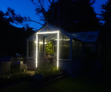
I strung one tape through the roof struts on one side of the greenhouse, behind my RPi camera so that the light would not blind it. The 5m strip provides plenty of light, enough to easily read a book, for instance. I put another strip round the doorway and this very adequately lights the small patio in front of the greenhouse and the lawn beyond. A third 5m strip will be applied to one of the walls to light the garden and the drive beyond.
I fancied being able to switch the lights on from the house (which is about 70m away) for instance, so I can illuminate the garden when I fancy a night time wander in the garden! I followed my well-
I could have based my unit on an Arduino type device (for me, usually the Adafruit Feather). One of the main advantages of such a device is that when power is applied it always runs the program downloaded into its memory without further intervention. However, the cost of such a device with WiFi and access to SD card storage can be substantially greater than the cost of a Pi Zero WiFi. Although a Python program normally needs to be loaded and run manually, it is quite possible to write a script to get the program to run on start up. One problem is that if the Zero is closed down, it is not possible to restart it remotely. Anyway, on this occasion, I am using the Pi Zero I had to hand!
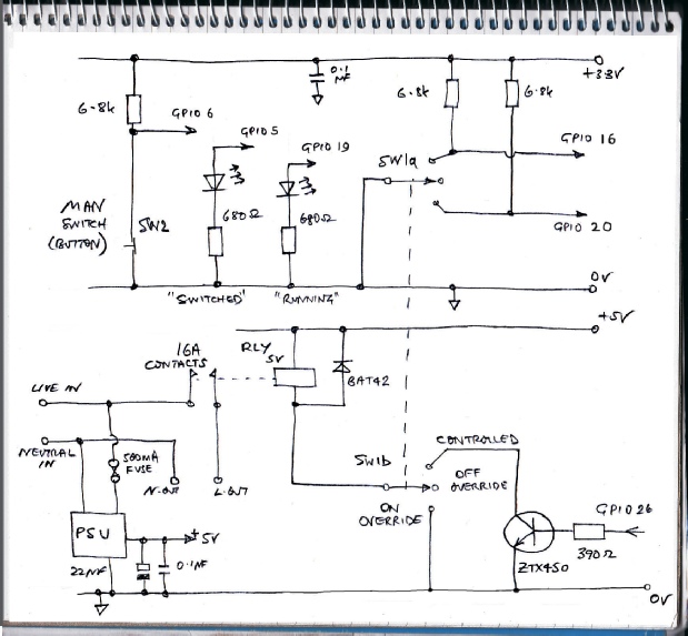
I have included a switch to override the Zero (permanently on or permanently off) and a button to turn the switch on via software so it can still be controlled remotely. An LED confirms the switch is turned on and another that the Zero is running and not crashed.
I dismantled a RPi power supply from its case and fitted it in a box with the Zero with a 500mA fuse on the mains supply side of the power unit (This was the smallest 20mm fuse I had to hand, 100mA would have been more than enough, I should think!).
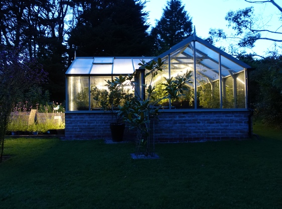
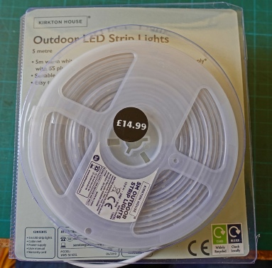
This simple LED tape lighting system is ideal for my greenhouse which doubles as a summerhouse where I dream of drinking a glass of wine on warm summer nights! I obtained three 5m LED tapes and power supplies from Aldi (Special Buys). These are not available at the time of writing but there are similar products available on the net, for example, on Ebay and Amazon, some cheaper too.
These strips are encased in a rubbery plastic case which would seem to give them a high degree of protection. The squashiness also enables clips to securely grip the tape without a great deal of pressure. The strips are IP44 rated. The second “4” indicates they are protected against water splashes but I can't see why they shouldn't be rated at “5”, which means protected against water from a nozzle in any direction. The power supply (a switched mode 12 volt 2A job) is, of course, not weatherproof.
The relay is rated at 16A so it can be used to switch anything which can be supplied from a 13A circuit. In this case, the three strips are rated at 24 Watts each which totals 72 Watts, so a 1A fuse would be plenty although the smallest I had to hand was 3A. (You should always use the smallest fuse practical to ensure the best protection.)
Circuit diagram
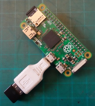
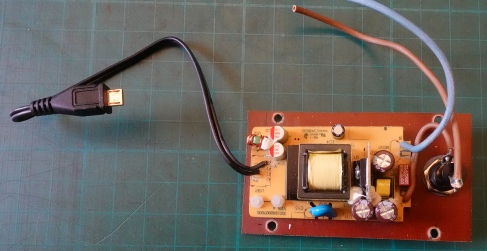
Above: Pi Zero non WiFi with WiFi module with micro USB adapter.
Below left: de-
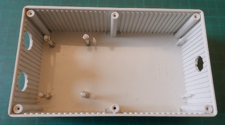
Below right: Hammond case drilled for cable glands etc.
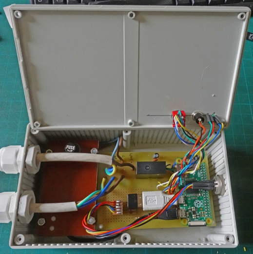
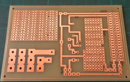
Above: pcb, the large pads are for the mains cables. As usual, I have included a lot of uncommitted pads as I can never decided exactly what connections I need to make at the pcb design stage!
Right: the pcb, with the Zero and the 5V power supply and the switches, LEDs etc. soldered in place. On the right is a 5-
I didn’t mention above that the relay is a Panasonic ALE1PB05 which I got from Rapid Electronics, part no. 60-