


Greenhouse monitoring and control - construction
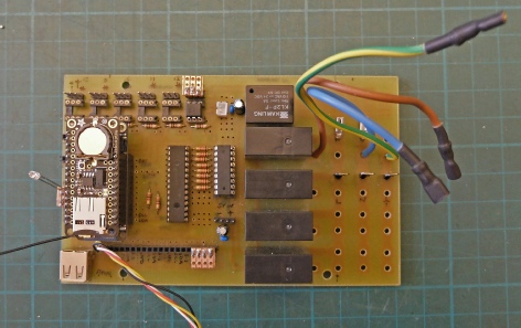
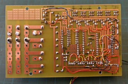
The first job is to design and make a pcb for the main circuit. I know from past experience that it will probably fit onto a piece of 100 x 160 material and so it proved! The circuit needed a fail number of links. On balance, I think the links are easier than making a double-sided board. The mains connections take up a fair amount of space and I have to allow for up to 13 amp capacity with plenty of margin (I hope). The mains comes in through 1/4 inch male spade connectors. The switched mains goes out to the sockets (“Cliffcon touch-proof”) via 3/16 inch female spades. This allows the pcb to be removed when required. I included some spare tracks for mods and corrected an error on the pcb with the battery polarity by cutting tracks and soldering wires (as usual!)
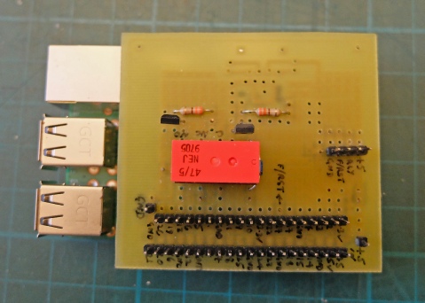
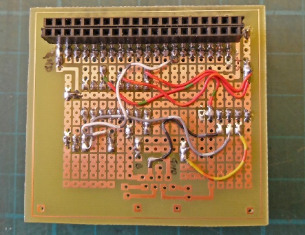
This is the pcb for the Raspberry Pi (it’s plugged onto the Pi in the left pic). Here I used a pcb I had already designed for the Pi. The only problem is soldering the 40-way socket on the “wrong” side of the pcb. By not allowing the socket to pass all the way through the pcb, it is possible to get a soldering iron in at the side to solder the pins. (I feel it is a bit of a lash up but it works!) The pcb was a sort of “universal type” so, again, there were plenty of wires. (I use wires from bundles of twisted pairs from old telephone systems. These are ideal if you can get them. They have single-cored tinned conductors, lots of colours and insulation that is heat resisting. They are great for bread boards but too small to be reliable in, say, an Arduino’s sockets.)
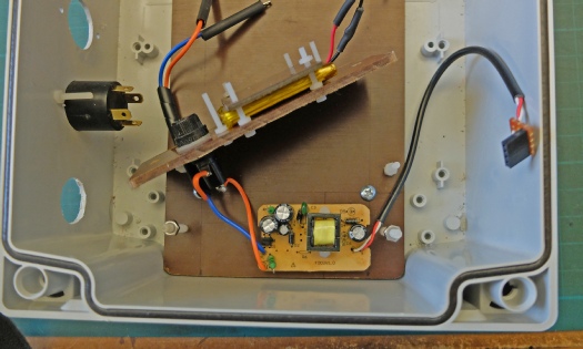
The picture on the left shows the power supply prised out of a “wall wart”. I have fitted a 20mm 200 mA fuse as the rest of the mains circuit is fused at 13 A. The supply is protected by a piece of Tufnol secured by nylon screws.
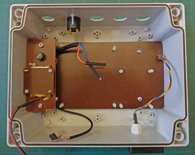
The right picture shows the Tufnol base board that the other circuits are attached to again with nylon screws. The Lipoly battery sits on top of the power supply.
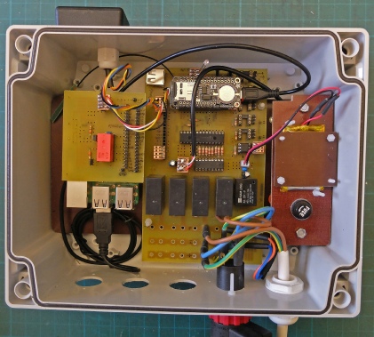
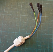
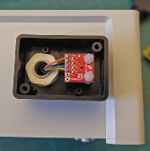
Left shows the unit with wiring still to do. Right is the mains input with female spade connectors. Far right is the temperature sensor in its own box.
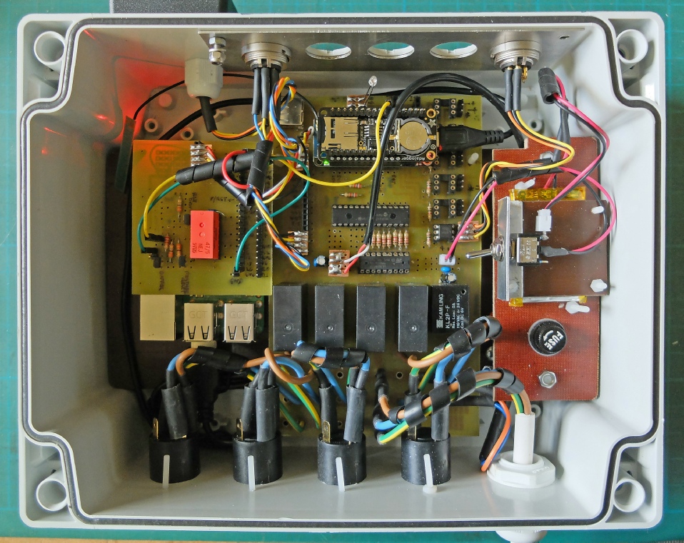
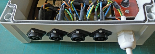
Above, are the four Cliffcon mains sockets. These are nice and compact, touch-proof and rated at 25 A.
Below, is the unit essentially finished apart from three 5-way DIN sockets which I am using to connect the remote sensors. I have included an aluminium panel to earth the sockets if that is necessary. I included a switch to disconnect the battery when the unit is disconnected from the mains (or the Pi is shut down) to prevent the battery going flat.