


 Home
Home

The starting point is a GRP mould taken off a US spec bumper. I found it easiest to do this with bumper on the car. I just took off the number plate and the side light/indicator units. I taped some card over the openings. I applied release wax to the bumper and then gel coat and a few layers of chopped strand mat. I get my materials from CFS (www.cfsnet.co.uk) mainly because they are based just up the road from me! The rubber bumper cover is a bit “wavy” so I had to sand and apply filler to the mould, once it had been taken off the bumper, to try to even things out.
I glassed on a couple of pieces of wood to keep the mould stable
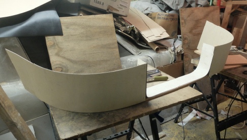
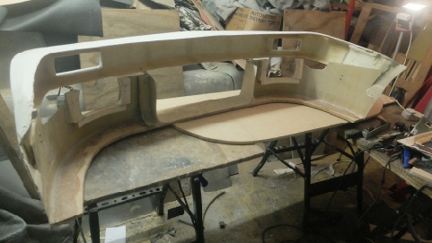
I then fitted the new bumper temporarily and took a piece of 1.5mm birch ply and bent it into shape under the bumper to get an idea of what the spoiler might look like. I jammed it into place with bits of wood and G-
I then cut out the shape in the MDF with a jig saw, smoothed it (a flexible body file is very useful here or if you are a posh cabinet maker, a compass plane (Stanley no. 20, I’ve always wanted one so if my wife is reading this…). I then applied polyurethane wood glue and stapled the ply to the MDF to keep it in place while the glue goes off. The glue is great and fills gaps but it must be clamped otherwise the foaming of the glue forces the parts apart. Also escaping foam once set is hard to remove unless your tools are sharp as it is very rubbery.
I didn’t mention that I applied the ply in two halves, leaving a gap for the air intake. I screwed and glued two pieces of softwood either side of this opening and sprang another piece of ply into the gap to produce the curved bottom of the opening.
I then tried the shape on the car. The ply needed some cut outs to clear some bodywork on the corners and cutouts for the fog/driving lamps.
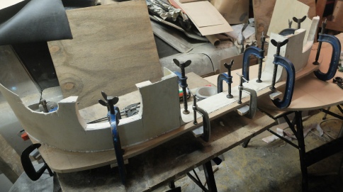
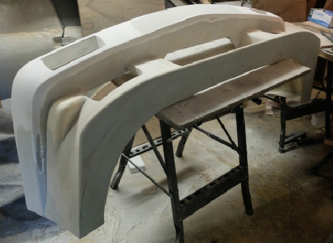
I then shaped more 12 mm MDF to form a splitter and glued that to the front of the spoiler with the gap-
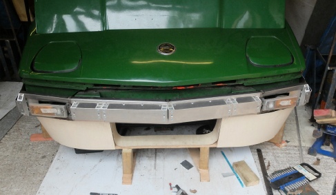
I put the spoiler back on the car, propped up in the correct position and used small brackets to hold the spoiler to the bumper skin. I then took the whole thing back to the workshop and backing up the gaps with anything which came to hand covered in gaffer tape so resin would not stick and gaffer taped in place, I gradually glassed the two halves together.
While it was still possible I put the whole thing back on the car and built up the shape where it was to fold round the edge of the wheel arch (I protected the paintwork with gaffer tape with ply and filler.
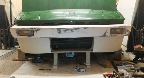
The shapes on the corner, needed to clear the bodywork corners, were added in polyurethane foam (Celotex or similar was what I used) as were extensions to the ends of the bumper cover so they reached the edge of the wheel arch.
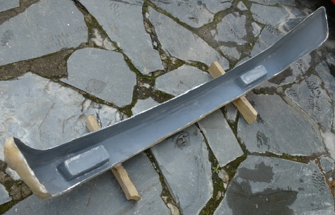
The next stage involved lots of filler and sanding repeated endlessly!
This is followed by spray painting with several coats of grey primer, followed by fine grain polyfila, rubbing down, more filler more rubbing down and so on.
In my mind I wanted something like the all in one front end like the Viper body kit shown in Roger William’s How to Improve TR7 etc. This looks like the original bumper but taken back to the wheel arch with a deep chip spoiler underneath. My idea was to try and mould such a design from scratch in GRP and fit it over a relatively light weight tube steel bumper (described here) which would replace the original. The side lights and indicators would fit on this frame and stay put when the front end was removed. I thought that while I was about it, I could mould a copy of the original bumper but perhaps slimmed down a bit and this could be easily swapped for the larger moulding if I wanted it to look stock at any time. (It might, for example, look too “Max Power” when completed and need a re-
In terms of fixing I was thinking Dzus clips but perhaps screws would be more practical and safer.
Now I know that the original bumper is flexibly mounted on a fixed central pivot and is supposed to balance out scuttle shake vibrations in the soft top. I just can’t believe that could be made to work other than at a particular speed over a particular surface. Anyway time will tell!
Getting rid of the original bumper which I read someone describe as weighing more than a small pony (according to my bathroom scales it’s actually 30 kilos) will make some difference to acceleration times and also reduce the polar moment of inertia which is good for handling. My guess is it will not noticeably increase the ride height.
The bumper frame is described here…