
 Home
Home
I have managed to find a use for all the Arduino pins except 0 and 1! The analog in pins are used as digital pins.
The inputs are: the indicator switch, the hazard switch, the lock/unlock switch (operates the door motors from inside the car), the receiver for the key fob transmitter, the alarm ultrasonic sensor, an on with ignition signal.
The outputs are 2 for the H-
The supply conditioning for the 5 volt electronics follows my usual practice of using a circuit I saw in Scientific American once. The choke should be about 10 micro H, I think. It may do some good. So far, I don’t seem to have experienced any Arduino crashes although I have many examples of Picaxe crashes which I put down to noise on the supply (but this is just a hunch).
The key fob transmitter and the receiver are made by Shark (type L54AF) and I don’t think they are available now (I did just find one on Ebay though!) However, there are numerous alternatives available on Ebay and elsewhere. The output is generally in the form of a relay and the contacts can be used with a resistor in the usual way (or using the “built in” resistor) to get the Arduino to respond.
The ultrasonic module is another item I had lying around and is probably not available now (model CS-
The n-
These are the features I wanted to build in (these involve both hardware and software aspects of the design):
Indicators operate when ignition is on only, hazard flashers at all times.
Alarm set/unset with remote -
Disconnecting the battery resets the alarm (just in case!)
Doors centrally locked with remote and alarm automatically set.
Locking doors with key does not set alarm (keeps it simple but could be done with 5-
Alarm procedures:
To set the alarm:
Ignition must be off. Press the remote, there is one beep from the buzzer, the indicator lights flash 3 times, the doors lock and the alarm LED flashes.
A “minor triggering” of the alarm senor will produce a warning beep, a “major” triggering will trigger the siren and flashing lights. After a set time the siren turns off. Alarm can then be re-
(To explain “major” and “minor”: the software counts the number of triggers in a set time. If they exceed a certain value that leads to a “minor” event if they exceed a certain greater value, a “major” event is triggered. This is to avoid false alarms and works reasonably well. It is a way of adjusting the sensitivity of the alarm in software. Even though ultrasonic transmitter and receiver are placed quite low down in the car, with the top down it may trigger if a person walks past the car so some reduction in sensitivity will always be needed.)
To un-
Press the remote. This will produce one beep and three flashes of the lights, the doors will unlock, the alarm LED will cease to flash and the interior light will come on for a fixed time before fading off (turning on the ignition turns off the light immediately but a separate circuit handles this).
To un-
Press the remote. The siren will cease and the lights stop flashing. The warning LED will turn off. There will be a rapid beeping which will be cancelled by turning the ignition on (this is to alert the user to the fact that the alarm has been triggered even if the alarm has automatically reset).
The alarm can only be reset with the remote (or by disconnecting the battery -
Next are details of the H-


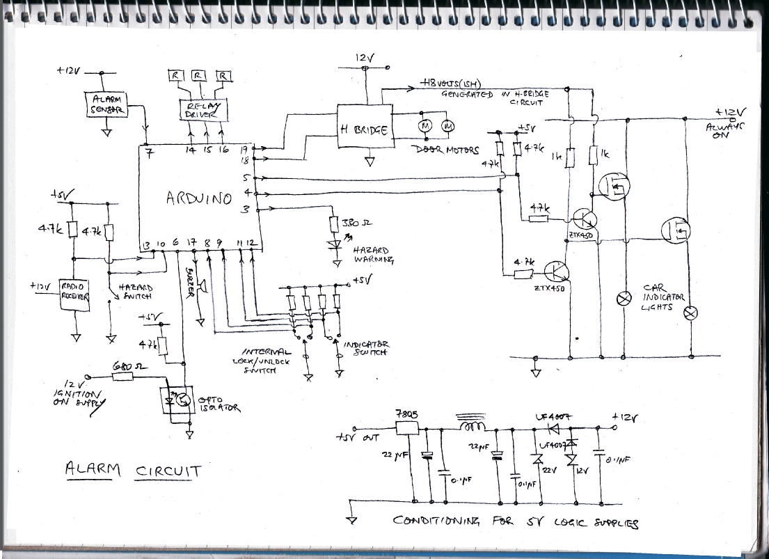
Alarm circuit